ENGLISH
DEUTSCH
ESPAÑOL
9
COD. 103202 Rev.4
COMPONENT PARTS
BEAD-BREAKERS
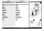
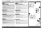
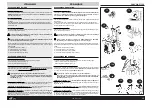
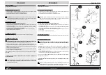
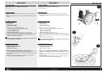
HYDRAULIC ROLLER BEAD-BREAKER (Fig. 2)
The “combined” version is equipped with hydraulic roller bead-breaker for the safe bead-breaking of
tyres mounted on alloy or painted rims. Characteristics:
» Nylon rollers (fig.1-13) mounted on fixed arms operating in perfect symmetry to help the operator
when preparing bead-breaking.
» The symmetrical action of the teflon rollers combined with the movement of the chuck allows opti-
mum efficiency when bead-breaking without causing any damage to the rim or tyre.
» The upper roller arm (14) can be disengaged by extracting the fixing pin to facilitate mounting
operations.
» The lower roller arm (15), as well as functioning as a bead-breaker, is particularly useful for pre-
venting tyres from beading back in during demounting and for helping the extraction process.
» The control panel governs all hydraulic movement (see the controls section - fig. 7 on pg. 10).
PNEUMATIC BEAD-BREAKER (Fig. 3)
The pneumatic bead-breaker is the traditional device for bead-breaking tyres from rims (fig. 3) and it is
composed of:
» Bead-breaking arm (10) driven pneumatically by a double action cylinder
» Bead-breaking plate (9) for bead-breaking tyres
» Anti-abrasive supports (11) for supporting the rim during bead-breaking
» Three position device which allows the width of opening of the bead-breaker plate to be easily and
quickly adjusted (12).
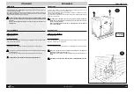
MOVABLE SELF-CENTRING CHUCK (Fig. 4)
The backwards and forwards movement of the chuck (fig. 4) (Sicam patent) is fundamental for bead-
breaking tyres, regardless of the rim format.
The chuck is powered pneumatically by two cylinders and is composed of:
» 4 sliding tracks (6) with locking jaws (5) for locking the rim internally or externally
» Rim anchoring device (8) which locks onto the chuck and is specially designed for working on
special rims and tyres
» Chuck plate (7) for rotating the rim in both directions without unlocking it.
The casing dimensions allow work on wheels of up to 1180 mm.
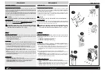
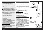
TILTING COLUMN (fig.5)
The tilting column has two (vertical) operating positions and carries the parts necessary for demount-
ing and (re-mounting) tyres:
» Sliding arm (1) for the horizontal positioning of the head
» Grip (3) for horizontal locking of the sliding arm and vertical “tyre” locking of the head and for
simultaneously setting an automatic gap of 3 mm (adjustable) from the rim flange.
» The tool head (2) for removing (and re-mounting) tyres from rims with the help of the bead-lifting
lever (see accessories supplied).
» The sliding roller (4), inserted inside the head, avoids any friction between the head and rim during
tyre mounting and demounting.
» Tongue: A special “protection tongue” designed for use with aluminium rims (see section “Accesso-
ries on request”).
EINZELTEILE
WULSTABDRÜCKER
HYDRAULISCHER ROLLEN-WULSTABDRÜCKER (Abb. 2)
Die Ausführung “COMBINED” verfügt über einen hydraulischen Rollenwulstabdrücker, mit dem die Reifen
sicher von legierten oder lackierten Felgen abgewulstet werden können. Seine Merkmale sind:
» Nylonrollen (Abb.1-13), auf starren Armen montiert, operieren vollkommen symmetrisch und
erleichtern so für den Bediener die einzelnen Abdrückvorbereitungen.
» Die symmetrische Funktion der Teflonrullen erlaubt zusammen mit der Bewegung des
Selbstzentrierers die optimale Leistungsfähigkeit während des Wulstab-drückens, ohne dabei auf
irgendeine Weise weder den Felgen noch dem Reifen zu beschädigen.
» Der obere Rollenträgerarm (14) kann durch Heraus-ziehen des Befestigungszapfens abgeboben
werden und erleichtert damit die Montageoperationen.
» Der untere Rollenträgerarm (15) dient außer zum allgemeinen Wulstabdrücken dazu, das Wiederein-
wulsten des Reifens zu vermeiden und das Heraus-ziehen zu erleichtern.
» Der Kommandoknüppel setzt alle hydraulischen Bewe-gungen in Gang (siehe Abschnitt
Kommandos, Abb. 7 auf Seite 10).
PNEUMATISCHER WULSTABDRÜCKER (Abb. 3)
Der pneumatische Wulstabdrücker ist eine traditionelle Vorrichtung zum Wulstabdrücken des Reifens
vom Felgen (Abb. 3) und besteht aus:
» Abdrückkralle (10), die von einem Doppelzylinder in Gang gesetzt wird;
» Klaue (9) für das Wulstabdrücken des Reifens
» Kratzsichere Halterungen (11) für das Aufsetzen des Felgens während des Wulstabdrückens
» Dreifach einstellbare Vorrichtung, mit der die Öffnungsweite der Abdrückklaue höchst einfach
eingestellt werden kann (12).
BEWEGLICHER SELBSTZENTRIERER (Abb. 4)
Die Vorwärts- und Rückwärtsbewegung des Selbstzen-trierers (Abb. 4) (SICAM-Patent) ist
ausschlaggebend für das Wulstabdrücken des Reifens unabhängig von der Felgenform.
Der Selbstzentrierer wird von zwei Zylindern pneumatisch in Gang gesetzt und besteht aus
» 4 beweglichen Schienen (6) mit Blockierungsrillen (5) für die Innen- und Außenblockierung des
Reifen-felgens;
» Verankerungsvorrichtung des Felgens (8), auf dem Selbstzentrierer festgemacht, wurde
zweckmäßig für das Arbeiten mit Spezialfelgen und -reifen entworfen und hergestellt
» Selbstzentriererplatte (7) zur Drehung des Felgens in beide Richtungen, ohne ihn zu entblocken.
Die Maße des Gehäuses sind für Reifen bis zu maximal 1180 mm Durchmesser bestimmt.
KIPPBARE TRAGSÄULE (Abb.5)
Die kippbare Tragsäule zweifache Betriebseinstellung (Senkrechtstellung), trägt die für das Abmontieren
des Reifens vom Felgen (und für die Neumontage) erforderlichen Einzelteile.
» Schwenkbarer Laufarm (1) für die Waagrechtstellung des Drehkopfs;
» Drehknopf (3) für die pneumatische Blockierung des Schiebearmes und der Drehkopfgruppe in
waagrechter und senkrechter Stellung und zur gleichzeitigen automatischen Einstellung des Abstands
(3 mm, regulierbar) vom Felgenrand;
» Drehkopf (2) für die Ab- und Aufmontage des Reifens vom und auf den Reifenfelgen mit Hilfe der
Wulstabdrückerstange (siehe Standardzubehör).
» Die Gleitrolle (4), im Innern des Drehkopfs eingebaut, um jegliche Reibung zwischen Felgen und
Drehkopf während des Ab- und Aufmontierens des Reifens zu vermeiden.
» Keil: Für Alluminiumfelgen ist ein “Spezial-Schutzkeil” vorgesehen (siehe Sonderzubehör)
PIEZAS COMPONENTES
DESTALONADORES
DESTALONADOR HIDRAULICO DE RODILLOS (fig.2)
La versión “combined” está equipada con un destalonador hidráulico de rodillos para destalonar con
seguridad los neumáticos montados sobre llantas de aleación o barnizadas. Las características son las
siguientes:
» Los Rodillos de nylon (fig.1-13) montados sobre brazos fijos, actúan de manera simétrica para
facilitar al operador durante las operaciones de destalonamiento.
» La función simétrica de los rodillos de teflón, acordada con el movimiento del autocentrado, permite
realizar la máxima y óptima operatividad durante el destalonamiento sin dañar ni la llanta ni el
neumático.
» El brazo portarodillo superior (14), sacando el perno sujetador, tiene la posibilidad de ser soltado
para facilitar las operaciones de montaje.
» El brazo portarodillo inferior (15) además de desarrollar la función general de destalonamiento,
es muy útil para evitar el retalonamiento del neumático y para facilitar su propia extracción.
» El cuadro de control activa todos los movimientos hidráulicos (véase la sección de los mandos y
véase Fig. 7 en pág. 10).
DESTALONADOR NEUMATICO (fig.3)
El Destalonador neumático es el dispositivo tradicional para destalonar el neumático de la llanta (fig. 3)
e incluye:
» Brazo Destalonador (10) accionado neumáticamente por un cilindro de doble efecto.
» Paleta (9) para el destalonamiento del neumático.
» Apoyos antiabrasivos (11) para apoyar la llanta durante la fase de destalonamiento.
» Dispositivo de 3 posiciones que consiente de variar la abertura de la paleta destalonadora con
gran facilidad y rapidez (12).
AUTOCENTRADO MOVIL (fig.4)
El movimiento hacia delante y hacia atrás del Autocentrado (Fig. 4) (patente Sicam) es indispensable
para realizar el destalonamiento del neumático, independentemente de la conformación de la llanta. El
Autocentrado es el dispositivo que se acciona neumáticamente gracias a dos cilindros y se compone
de:
» 4 recorridos móviles (6) con cuñas de bloqueo (5) para el bloqueo interior y exterior de la llanta.
» Un dispositivo de anclaje de la llanta (8), bloqueado sobre el autocentrado ideado adrede y
realizado para obrar sobre llantas y neumáticos especiales.
» Un plato autocentrado (7) para girar la llanta en los dos sentidos sin desbloquearla.
Las dimensiones de la caja consienten de actuar sobre ruedas con un diámetro máximo de 1180
mm.
COLUMNA VOLCABLE (fig.5)
La Columna Volcable utilizable en 2 posiciones (verticales) soporta los componentes necesarios para
desmontar el neumático de la llanta (y para montarlo nuevamente):
» El Brazo corredizo (1) para la colocación horizontal de la Torre;
» El Botón de bloqueo neumático (3) permite obtener con una única operación sea la distancia de 3
mm (ajustables) desde el borde de la llanta, sea el bloqueo horizontal del brazo deslizante y vertical
del cuerpo de la torre.
» La Torre (2) para quitar con el auxilio de la palanca levanta-talones (vea accesorios de equipo) el
neumático de la llanta (y para montarlo nuevamente).
» El Rodillo de deslizamiento (4) introducido en la ranura de la Torre, permite actuar sobre el neumático
evitando el frotamiento entre la llanta y la torre durante las operaciones de montaje y desmontaje.
» Lengüeta: Para las llantas de aluminio está prevista una “Lengüeta Protectora” especial (véase la
sección titulada “Accesorios de equipo”).
Summary of Contents for FALCO AF1718
Page 36: ...N 102180 Rev 6 COMBINED FALCOAF 1718 AF1720 IT RACING ITE RACING...
Page 37: ...N 102583 Rev 6 COMBINED FALCOAF 1718 AF1720 IT RACING ITE RACING...
Page 38: ...N 101051 Rev 5 COMBINED FALCOAF 1718 AF1720 IT RACING ITE RACING...
Page 39: ...N 101065 Rev 5 COMBINED FALCOAF 1718 AF1720 IT RACING ITE RACING...
Page 40: ...N 101045 Rev 13 OPTIONAL...
Page 41: ...N 102181 Rev 4 COMBINED FALCOAF 1718 AF1720 IT RACING ITE RACING...
Page 42: ...N 101074 Rev 5 COMBINED FALCOAF 1718 AF1720 IT RACING ITE RACING...
Page 43: ...N 101289 Rev 4 COMBINED FALCOAF 1718 AF1720 IT RACING ITE RACING...
Page 44: ...N 101122 Rev 0 COMBINED FALCOAF 1718 AF1720 IT RACING ITE RACING...
Page 45: ...N 101120 Rev 7 COMBINED FALCOAF 1718 AF1720 IT RACING ITE RACING...
Page 46: ...N 101519 Rev 2 COMBINED FALCOAF 1718 AF1720 IT RACING ITE RACING...
Page 47: ...N 100933 01 Rev 0 COMBINED FALCOAF 1718 AF1720 IT RACING ITE RACING...
Page 48: ...N 100933 02 Rev 0 COMBINED FALCOAF 1718 AF1720 IT RACING ITE RACING...
Page 49: ...N 100933 03 Rev 0 COMBINED FALCOAF 1718 AF1720 IT RACING ITE RACING...
Page 50: ...N 100933 04 Rev 0 COMBINED FALCOAF 1718 AF1720 IT RACING ITE RACING...
Page 51: ...N 101125 01 Rev 0 COMBINED FALCOAF 1718 AF1720 IT RACING ITE RACING...
Page 52: ...N 101125 02 Rev 0 COMBINED FALCOAF 1718 AF1720 IT RACING ITE RACING...
Page 53: ...N 101125 03 Rev 0 COMBINED FALCOAF 1718 AF1720 IT RACING ITE RACING...


