background image

Shining 3D Transcan-C_User Manual_V1.4.2 

53 


7.4.2.


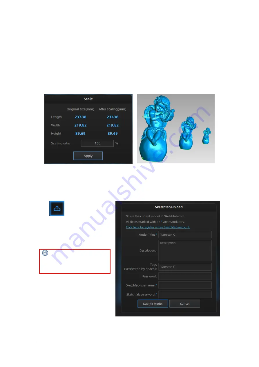
Scale Data 

Scaling the volume of scanned data, while the number of triangles, the level of detail of the scan and 
size of data will not be actually changed. 
 
By default, the scale is 100% and will be exported with millimeters for reference. 
 
The value display represents the dimensions of the smallest box containing the data oriented to the 
reference axis. 


Scale window


Scale result


7.4.3.


Share Data 

Click 

  after mesh to share data 

to  Sketchfab,  it  will  show  the  dialog  as 
below.  A  model  title,  username  and 
user  password  are  required.  Register 
and view the shared model at 
http://sketchfab.com. 
 

Note: 

 
Data  is  saved  as  .STL  does  NOT 
contain texture


Summary of Contents for Transcan-C

Page 1: ...Shining 3D Transcan C_User Manual_V1 4 2 1 Transcan C User Manual V1 4 2 ...

Page 2: ...stalling operating and maintaining the product including the Device software or other products provided by the Company to which the Manual is applicable The Manual does not serve as the quality guaranty for the product While the Company makes all efforts to ensure the applicability of the content of the Manual it reserves the right to interpret and modify the content of the Manual and possible err...

Page 3: ...on 14 4 Calibrate the Scanner 18 4 1 Precautions and Use 18 4 2 Operation 18 5 Scanning 23 5 1 Preparation 23 5 2 Before Scanning 24 5 3 Scan 28 6 Project Group 32 6 1 Create Import Projects 32 6 2 Rename a Project 32 6 3 Delete 32 6 4 Create Split A Group 33 6 5 Edit Data 34 6 6 Global Optimization 34 6 7 Alignment 34 7 Post Process 36 7 1 Mesh Watertight Unwater tight 36 7 2 Data Post Process 38...

Page 4: ...er saving mode of the computer 1 2 Hardware Installation Unpack and set up your scanner before getting started with scanning 1 2 1 Assemble Scanner 1 Open the tripod and place it on the ground The three tripods can be extended and retracted After adjusting the height lock and fix the tripod 2 If the height is still too high or too low loosen the lock 2 to adjust and fasten vertical slide rod to an...

Page 5: ...the lock after the adjustment is complete 1 2 2 Connect the Scanner 1 Connect the power cord and cables Confirm that power switch is not pressed Connect the power cord port and the adapter port first Inserted adapter socket into the device port Insert the power cord triangular plug into the plug or socket Connect the computer USB 3 0 port and device socket with the device connection cable If using...

Page 6: ...erface next to the labeled SS is the USB3 0 interface 2 Turntable connection Insert the turntable connection cable into the turntable port Insert turntable connection cable into computer USB port Insert the turntable power cable into the turntable port ...

Page 7: ...wer button to turn on the device and the switch light will be on 2 Press power button again to turn off the device and the switch light turns off After installing the software connect the device to the computer and start it up the following devices are displayed in the Device Manager ...

Page 8: ...evice is connected and keeps prompting Device offline Check power connection status Check if USB 3 0 is connected Install the camera driver manually if a device with a question mark or exclamation point is found in the Device Manager After the device is powered off unplug the USB cable then re power and plug in the USB cable ...

Page 9: ...o complete the software installation 3 After the software is installed a shortcut will be created on your desktop Double click to open the software 2 3 Firmware Update When the scanner firmware is incompatible a message will appear when software is open Click Upgrade and follow the instruction to update the device firmware Firmware updating will take around 3 mins Power off the device after upgrad...

Page 10: ...mware update after successful recovery If recovery fails turn off the power of the scanner and reconnect the scanner to restart the software for upgrading 2 4 Update the Software When a new version is available a pop up will show when you start the software to remind you update your software to the latest version Note After clicking Download Now the software will be downloaded do not close the sof...

Page 11: ...pdate Reminder 2 5 User Account Double click to enter the software Register for an account firstly if you do not have a Shining 3D User Account Note After logging in the login interface will no longer be displayed and one can log in automatically ...

Page 12: ...eting and Promotion Agreement Optional Step 4 Click Sign up 2 5 2 Login Use your registered account to log in Log in by password or verification code 2 5 3 Activate the Scanner Device activation is required in your initial use There are 2 ways 1 Online activation is recommended if your computer is connected to the internet 2 If there is an issue with network connection use Offline Activation to co...

Page 13: ...ortable hard disk hereinafter referred to as the disk to the computer installed with EXScan before offline activation 2 Click to enter offline activation interface 3 Export C2V file Click Export to save generated C2V file to the disk 4 Login your user account at https passport shining3d com login using the internet connected computer 5 Click Offline Activation after logging in successfully 1 Impor...

Page 14: ...Calibration Scanning Post processing Measurement Maximize Minimize Community Settings Help Camera Device Scan Data Fit to view Mouse operation prompts 2 6 2 Reconnect the Scanner When the device is offline meaning the scanner is not connected to PC check the connection restart the software and click the refresh button to reconnect Device offline or connection loose ...

Page 15: ...vices according to the following figure 1 Lay the calibration board flat on the table with the desired side facing the scanner 2 Adjust the bracket of the calibration board to the marking angle and place it to the first calibration position 3 Place the calibration plate on the stand 4 Move the scanner to the front position of the calibration board or move the calibration plate bracket and calibrat...

Page 16: ...he scanner aiming direction should be perpendicular to the calibration board 300mm Ensure the top and bottom edges of projected area aligns with two rows of points on the calibration board and the projected cross should aim at the center point The scanner aiming direction should be perpendicular to the calibration board 150mm 300mm 7 Face the scanner with white side of the calibration board and tu...

Page 17: ...angles of the camera so that the intersection of the black cross is basically on the red vertical line of the camera window and then tighten the screws 150mm 300mm Allen key specific location Two sizes of Allen keys 10 Unscrew the screw on the aperture and turn the aperture to adjust the brightness of the left and right camera windows The recommended value is 5 6 When the adjustment is complete ti...

Page 18: ... 11 Lose the screw on the focal length and double click the left and right camera windows to zoom in and check the clarity of the circle border After the adjustment is completed tighten the screw to prevent loosening to limit the scanning effect ...

Page 19: ...ill enter the calibration interface automatically If there is no calibration data click quit the software will prompt No calibration data please calibrate Different calibration boards are used for scanning ranges of 300mm and 150mm Select the corresponding calibration board as shown in the calibration interface Note 1 After the calibration is complete put the calibration board way in its velvet ba...

Page 20: ... windows turn slightly red Place the calibration board according to the following figure Ensure that the placed position is consistent with that shown in the figure The calibration board can be divided into upper lower left and right In the first step make sure that the five big circles in the red box are placed near the bottom of the calibration pad as shown in the figure below Ensure that the ca...

Page 21: ...rd bracket rotate the calibration board 90 clockwise and put it on the calibration board bracket Click Previous Step to go back to the previous step to capture again For Step 3 to Step 10 collect data according to the prompts After the acquisition is completed carry out calibration calculation The camera calibration results are as follows ...

Page 22: ...s bar on the white balance interface to adjust the brightness of the windows Adjust the brightness until the back of the calibration board in the window is slightly red If the brightness is insufficient or too bright adjust the ambient light or light box brightness Click White balance test The white balance verification is complete when the white balance calibration is successful To obtain good te...

Page 23: ...Shining 3D Transcan C_User Manual_V1 4 2 22 Click Exit on the calibration interface to enter the scan new project ...

Page 24: ... markers in each frame one scanning field of view Control the number of markers seen on the camera view Stick markers in a random non linear pattern see example below Four markers are required for public area alignment Markers should be stuck on the flat surface area and keep the marker surface flat Use the markers provided with the device only Other markers can result bad accuracy or not to be se...

Page 25: ... project Note Under texture scan if you do not use light box ensure the illumination and brightness casted on the scanned object are even Under texture scan do not use colored light source such as colored light in indoor environment 5 2 2 Working Distance Before starting scanning make sure that the scanned object is placed properly check the black cross projected on the object in the camera viewpo...

Page 26: ...played on the interface and only the objects corresponding to this global marker file can be scanned at this time only the single piece mark and the rotary table global marker scanning mode global markers can be edited Adjust Brightness Click and drag the button to adjust the brightness The correct brightness setting will depend on the lighting in the environment and the texture of the object Drag...

Page 27: ...er of steps according to the features of the objects Note Using more turntable steps will help scan more complete data in some angles but NOT more accurate Turntable Speed Turntable speed Set to adjust turntable speed 6 is set by default Higher value is with higher speed Skip Turntable Location Verify Use existing axis calibration data After it is enabled the existing axis data will be used for al...

Page 28: ...argets need to be recognized between 2 neighboring scans Note The object needs to be small without covering the coded targets put the object on the middle of the turntable and make sure the object will not move during scanning If you choose turntable coded target alignment the scanner head is requested to fix on the tripod to scan Feature Alignment When the distance between turntable and scanner i...

Page 29: ...e if a Global Marker File has been loaded during the project creation 5 3 Scan 5 3 1 Scanning Button Click the button or press Space key to start scanning When the scan is completed the data is automatically saved in the project file Make sure the relative position does not change during the scan When auto scan mode is scanning you can click the button to stop the current scan The current data wil...

Page 30: ...t deleted data Click the button or press Space key to save data and exit editing The edited data is saved in the project file Cancel editions on the data 5 3 3 Right Click Menu Right click on the interface and the following right click menu appears Function Description Select all deselect deselect delete selected Same functions as editing can be operated by shortcut keys Suitable view Data is cent...

Page 31: ...loud fitting The direction of the plane will be calculated by the software according to the direction of point cloud Creating straight line Press Shift left click to draw a line and generate the cut plane according to the line By Marker Press Shift left click to select markers 3 markers or more are required to generate the cut plane Cut Plane setting Rotation axis Cut plane can be rotated around t...

Page 32: ... to enter the cut plane setting after quitting the cut plane interface Hide Show cut plane After creating the cut plane hide or show the cut plane by right click Note Editing markers is not available for cutting plane When cutting plane is present the data below the normal direction of the cutting plane cannot be scanned except for the markers ...

Page 33: ...ick the Project button to create or open a project Click on the project tree or on the project button create a new project or import a project into the work Imported data will be copied in the work folder and appear on the project tree New project will create a new entry in the project tree and a new project file in the work folder 6 2 Rename a Project Right click on the project on the tree to ren...

Page 34: ...a list or on the scanned model Shift Ctrl Left mouse Multi select in the data list Create or split group Hide or display data After creating the group all the selected data belong to it Right click the group or data to view drop down menu Note The data captured by turntable scan mode will belong to one group by default The group can be deleted or separated You could click the scan model to select ...

Page 35: ...rkers the data of a project will automatically align with the marker positions If not an automatic alignment will be calculated with a best fit of the single scan to the previous scans of the project according to the geometric features If the object is not with enough geometric features you can use manual alignment Click the button to open the Manual Alignment interface Select the project in the f...

Page 36: ...nment You could choose marker alignment if the projectors are with markers There shall be at least 3 common markers in two projects otherwise the alignment will fail Software will align the projects according to the positions of those markers automatically Click Apply to align Click Next the aligned projects will merge to a group you could continue further alignment Click Cancel to recall the alig...

Page 37: ...tight All holes will be filled automatically The data can directly be 3D printed Unclosed model stays the way it is scanned Processing time is quicker than Watertight Watertight quality Choose quality TEXTURE WATERTIGHT The texture capture is separate from the 3d data capture If the texture has been captured it will still be displayed on areas where holes are filled in the mesh processing If the t...

Page 38: ...s disable the function Filter Optimize data Filter 10 Filter 60 Remove small floating parts Remove small floating parts in the scan data Max triangles Set the max plate number to get the mesh model s triangle plate number which is within the configured plate number Fill small hole For objects with tiny holes smaller than 10 mm use the function to fill tiny hole to make the scanned image look bette...

Page 39: ...markers fill 7 2 Data Post Process 7 2 1 Mesh Editing The mesh can be edited Select delete Hole filling Sharpen Smooth Simplification Multiview MESH SELECT DELETE Press Shift Left mouse to select data and enter the selection menu CTRL Left mouse Deselect a selected region CLOUDS SELECT DELETE SHIFT Left mouse Select unwanted data the selected section will be displayed in red as shown below CTRL Le...

Page 40: ...o delete selected data Undo You can only undo the most recently deleted data Apply edit Click the button or space bar to apply the edition and exit edit mode Cancel edit Undo all editors and exit edit mode 7 2 2 Texture Adjustment When the mesh model has been generated use the cursors to change the Brightness and or contrast of the texture from 100 to 100 The default value is 0 for both Brightness...

Page 41: ...ck Apply button to simplify data preview the result of current setting Click Confirm button to apply the Simplification setting Click Cancel button to quit and go back to the original data Multiple operations on Simplification the result will not be added It will always operate on the original data simplification 0 simplification 90 7 2 4 Mesh Optimization Mesh optimization can optimize the qualit...

Page 42: ...tton to quit and go back to the original data Multiple operations on Mesh Optimization the result will not be added It will always operate on the original data 7 2 5 Smooth Smooth the possible noise on the surface of the scan data It might remove some small details or smooth some sharp edges at the same time The example of before and after smoothing is shown below Run 2 times data will be smoothed...

Page 43: ...gonal length of the floating part 10 MAX L 10 2 Diagram of removing floating parts shows as below Original data Remove floating part 10 Remove floating part 50 Remove floating part 100 Click Apply button to remove floating part preview the result of current settings Click Confirm button to apply the remove floating part setting Click Cancel button to quit and go back to the original data Multiple ...

Page 44: ...nt position and the normal of the 2 last rows of triangles forming the boundary Effect of Curvature Tangent or Flat Click Apply button to auto fill hole preview the result of current setting Click Confirm button to apply the Auto hole filling setting Click Cancel button to quit and go back to the original data Manual Hole Filling The hole edges are displayed green and get red after picking The num...

Page 45: ...e Remapping to display the Texture menu Mesh edition of simplification hole filling on texture scanned data will affect the texture render By doing the texture remapping the texture information will be reapplied on the mesh If post processing operations have been performed it is recommended to perform texture remapping before saving data 7 2 8 Texture Layout Optimization Choose Texture Layout Opti...

Page 46: ...t 7 2 9 Return to Scanning Mode To continue scanning edit data or mesh again you need to exit the post processing mode and click Scan on the navigation bar to return to the scanning mode interface and the mesh data in the post processing interface will be cleared Note Mesh data in the post processing interface will not be automatically saved 7 3 Measurement After meshing the Measurement menu will ...

Page 47: ...lose the window The features created displaying in gray the selected features are in red In the feature list click delete button to remove Delete action cannot undo Feature Creation method Requirement Description Point Selected Points Click on the data to select a point Click create to create a point Line Plane Interface Line and Plane should be created in advanced Click on the created line or sel...

Page 48: ...ne Fit Line should be created in advanced The plane generated includes the point and the line The line should be created in advanced Click on the line previously created or select it from the drop down Click on the data to select a point or click on a feature point previously created In the Choice list select one of the elements to reselect it Feature creation failed Error code 6 the point selecte...

Page 49: ...al position Click OK to confirm the transformation Tips Start from data reposition offset to 0 0 0 Edit rotations prior to transformation Change the view normal to a reference plane to change the corresponding angle 3 2 1 Movement Prior to 3 2 1 movement the creation of a plane line not normal to the plane and point are required 3 2 1 movement plane line point alignment aligns the data by deletion...

Page 50: ...n Beware the direction of the line to match it to the or axis The projection of the line to the first plane will be parallel to the corresponding axis Select a Point in the drop down menu The data will be translated to match the point with the origin point coordinate 0 0 0 Click Align to perform the transformation Data after 3 2 1 movement Click Reset to cancel Click Apply to confirm the transform...

Page 51: ...anes SURFACE AREA Press Shift LMB to select an area press Ctrl LMB to unselect Ctrl A to select all Click Calculate to display the Area value of the selected data in mm 2 Redo the selection and click calculate again to update Surface Area menu VOLUME This tool calculates the volume contains in a watertight mesh It returns the volume in mm 3 and the coordinates of the smallest box parallel to the g...

Page 52: ...Shining 3D Transcan C_User Manual_V1 4 2 51 Volume menu Prior to the calculation make sure the file is watertight no holes File not watertight alert ...

Page 53: ...t process in another software ASC whole No optimized point cloud scan asc Inspection Fast export no post processing needed in hand held mode Large data to post process in another software Complex data to post process in another software STL No Mesh scan stl 3D printing watertight mesh data Reverse Engineering Compatibility with most mesh editing software OBJ Yes separated Mesh Texture Matching fil...

Page 54: ...l be exported with millimeters for reference The value display represents the dimensions of the smallest box containing the data oriented to the reference axis Scale window Scale result 7 4 3 Share Data Click after mesh to share data to Sketchfab it will show the dialog as below A model title username and user password are required Register and view the shared model at http sketchfab com Note Data...

Page 55: ...third party software together with the Scanner To get one contact us to buy it Geomagic Control X Process stl data create feature and measure feature data Verisurf A 3D measurement platform for manufacturing inspection tool building and reverse engineering Geomagic Design X Obtain stl data Create facets or surfaces to finish reverse engineering Geomagic Essentials Extract the feature you want and ...

Page 56: ...ta with the same control as EXScan C software Model Preview STL OBJ PLY ASC or 3MF can be loaded files from 3rd party software might fail to be loaded In this case we recommend Meshlab a free mesh software editor or upload to sketchfab Note To load a OBJ textured file make sure to have the MTL and JPG files with the same name and in the same folder than the OBJ ...

Page 57: ...s improve the quality and user experience of device we hope to be allowed to collect usage experience information This information will not contain your personal information or scanned data and will not be accessible to any third party Factory Default All settings can be restored to the initial settings and the software will automatically restart About View related software release information con...

Page 58: ...e scan area has at least 4 points 2 What if the alignment fails without markers when the turntable has rotated several circles Solution Try to make sure there are at least 1 3 overlap between the current scan area and the previous scan area and the object surface should be featured For objects which are symmetric and without rich features using mark points or manual merger is recommended 3 How to ...

Page 59: ...ently in the proper position and do not squeeze it Prepare precautions like sunscreen rain proof shock proof and etc No matter on sunny or rainy days If the device could not function correctly fixing the device by opening it by yourself is not allowed The device shall be repaired by professional technicians or under their instruction You should send the device to facilities with qualification for ...

Page 60: ...quarters SHINING 3D Tech Co Ltd Hangzhou China Phone 86 571 82999050 Add No 1398 Xiangbin Road Wenyan Xiaoshan Hangzhou Zhejiang China 311258 EMEA Region SHINING 3D Technology GmbH Stuttgart Germany Phone 49 711 28444089 Add Breitwiesenstraße 28 70565 Stuttgart Germany Americas Region SHINING 3D Technology Inc San Francisco United States Phone 1 415 259 4787 Add 1740 Cesar Chavez St Unit D San Fra...

Reviews: