background image

35

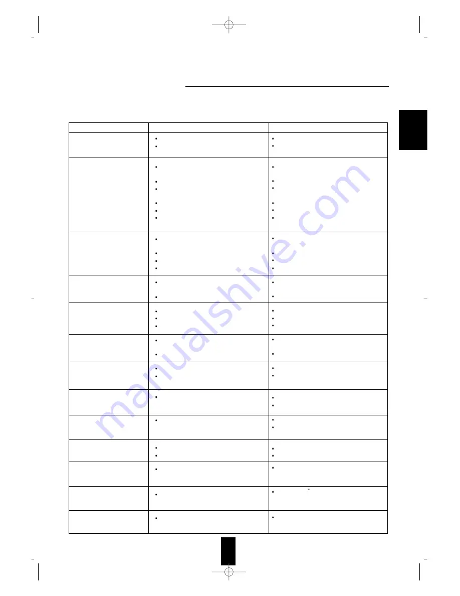
PROBLEM

POSSIBLE CAUSE

REMEDY

No power

No sound

No sound from the rear speakers

No sound from the center
speaker

Stations cannot be received

Preset stations cannot be
received

Poor FM reception

Continuous hissing noise during
FM reception, especially when a
stereo broadcast is received.

Continuous or intermittent
hissing noise during AM
reception, especially at night.

Remote control unit does not
operate.

Other Sherwood components do
not react to remote control
commands.

A video label cannot be
displayed.

OSD function cannot be
availabe.

The AC input cord is disconnected.
Poor connection at AC wall outlet or the

outlet is inactive.

The speaker cords are disconnected.

The master volume is adjusted too low.
The MUTE button is pressed to ON.

The digital input is not selected correctly
Incorrect selection of input source.
Incorrect connections between the

components.

Surround mode is switched off.(normal stereo

mode)

Master volume and rear level are too low.
Monaural source is used.
Dolby 3 Stereo mode is selected.

DTS,Dolby Digital, Dolby Pro Logic or

Dolby 3 Stereo mode is not selected.

Master volume and center level are too low.

No antenna is connected.
The desired station frequency is not tuned in.
Antenna is in wrong position.

An incorrect station frequency has been

memorized.

The memorized stations are cleared.

No antenna is connected. 
The antenna is not positioned for the best

reception.

Weak signals.

Noise is caused by motors, fluorescent lamps

or lightning, etc.

Batteries are not loaded or exhausted.
The remote sensor is obstructed.

DIGI LINK connections are not made

properly.

Mulfunction due to external influences such

as static electricity, etc.

Video connections between this unit and the

monitor TV are not made correctly.

Connect cord securely.
Check the outlet using a lamp or another

appliance.

Check the speaker connections on the power

amplifier.

Adjust the master volume.
Press the MUTE button to cancel the muting

effect.

Select the digital input correctly.
Select the desired input source correctly.
Make connections correctly.

Select a surround mode.

Adjust master volume and rear level.
Select a stereo or surround source.
Select the desired surround mode.

Select the desired surround mode.

Adjust master volume and center level.

Connect an antenna.
Tune in the desired station frequency.
Move antenna and retry tuning.

Memorize the correct station frequency.

Memorize the stations again.

Connect an antenna.
Change the position of the antenna.

Change the position of the antenna.
Install an outdoor FM antenna.

Keep the receiver away from noise sources.
Install an outdoor AM antenna.

Replace the batteries.
Remove the obstacle.

Make proper DIGI LINK connections.

Clear it using To clear a video label” (Refer to

“Rectifying or clearing a video label” on page
28)

Make proper video connections.

If a fault occurs, run through the table below before taking your unit for repair.
If the fault persists, attempt to solve it by switching the unit off and on again.  If this fails to resolve the situation, consult
your dealer. Under no circumstances should you repair the unit yourself as this will invalidate the warranty!

ENGLISH

Summary of Contents for AVP-9080

Page 1: ...liance to rain or moisture Caution Do not block ventilation openings or stack other equipment on the top FOR U S A Note to CATV System Installer This reminder is provided to call the CATV system insta...

Page 2: ...the power point is earthed and that the installation is completely safe For your safety if in any doubt about the effective earthing of the power point consult a qualified electrician PAN EUROPEAN UNI...

Page 3: ...RANGE 11 LOADING BATTERIES 11 ENTERING A SET UP CODE 12 Operations LISTENING TO A PROGRAM SOURCE 13 SURROUND SOUND 16 ENJOYING SURROUND SOUND 17 LISTENING TO RADIO BROADCASTS 22 LISTENING TO RDS BROA...

Page 4: ...to the DIGI LINK jack of the external Sherwood component that uses the DIGI LINK ll or lll remote control system CONNECTING ANTENNAS DIGI LINK STEREO DOUBLE CASSETTE DECK DD 5080C AUTO REVERSE PLAY A...

Page 5: ...ack will be output in only the S VIDEO REC jack and a signal input into the normal VIDEO PLAY or the COMPONENT VIDEO IN jack will be also output in only its own VIDEO REC or OUT jack However the video...

Page 6: ...quired by the power amplifier or powered subwoofer used Components such as CD LD or DVD capable of digital output of DTS Digital Surround Dolby Digital PCM or digital RF should be connected to these i...

Page 7: ...TEREO DIGITAL PRO LOGIC INPUT SELECTOR KNOB TONE DIRECT BUTTON INDICATOR DYNAMIC RANGE BUTTON INDICATOR DOOR OPEN BUTTON MASTER VOLUME KNOB STEREO SURROUND OFF BUTTON DSP MODE BUTTON DOLBY PRO LOGIC B...

Page 8: ...ponents that are remote compatible Notes The set up code for each component must be entered before operation For set up codes product identification codes please refer to Set Up Code Tables in the ope...

Page 9: ...RWARD FORWARD PLAY REVERSE PLAY RECORD Button symbols pressing PLAY etc on CD player or tape deck CD or TAPE 2 MONITOR is selected automatically without selecting the input source and then PLAY etc st...

Page 10: ...he component you want to operate 3 Turn on the components you want to operate 2 Press the button corresponding to the operation you want while aiming the remote control at the REMOTE SENSOR on the com...

Page 11: ...el 12 5 Find the set up code for your component referring to Set Up Code Tables in the operating manual of this remote control 2 Turn on the component you want to control Note Some components includin...

Page 12: ...MONITOR button is set to on and TAPE 2 MONITOR button on the front panel lights up in green other inputs can not be heard from the speakers To listen to a input source other than TAPE 2 MONITOR be sur...

Page 13: ...AYER only Opt ical Coax ial To play back the laser disc encoded into the Dolby Digital format in the Dolby Digital mode you should select the RF input as the desired digital input In the normal stereo...

Page 14: ...adjusted together If the TONE FLAT button is pressed the bass and the treble of the selected channel are all adjusted to the flat level 0 dB If the tone display disappears start from the step 7 again...

Page 15: ...group music This unit has 8 different surround modes to allow you to enjoy surround sound with various program sources DTS DOLBY DIGITAL DOLBY PRO LOGIC DOLBY 3 STEREO THEATER HALL STADIUM CHURCH DTS...

Page 16: ...ges as follows Surround sound effect will not work properly if the signal passes through a graphic equalizer Please refer to your equalizer operating instructions for guidance on switching off or defe...

Page 17: ...s displayed When using a relatively large center speaker full range speaker When using a relatively small center speaker which cannot reproduce the low range bass sounds deeply When not using a center...

Page 18: ...desired Repeat the above steps 11 and 12 to adjust other channel levels The desired rear speaker mode is memorized and then it enters the subwoofer mode If the rear speaker display disappears start f...

Page 19: ...n the Dolby Pro Logic mode Rear delay time 15 ms If the center or the rear speaker s is are not at the same distance from the prime listening position as the front speakers increase or decrease the ce...

Page 20: ...ay If the headphones are plugged while playing back the Dolby Digital program sources in the Dolby Digital mode it will be automatically in the DD Stereo mode but Dolby Digital is displayed still and...

Page 21: ...essing the BAND button without selecting the Tune the tuner will be selected automatically Tuning mode Tuning Mode lights up Preset tuning mode Preset Mode lights up Manual tuning is useful when you a...

Page 22: ...istening to FM broadcasts The unit will start scanning the stations in the preset sequence and each station is received for 5 seconds At the desired station press this button again to stop scanning Sc...

Page 23: ...e Tp search mode 1 RDS search TP search PTY search In the FM mode select the PTY search mode 1 RDS Radio Data System is method for sending information signals together with the transmitter signals You...

Page 24: ...services In no station is found NO PROGRAM is displayed If one of the preset stations is broadcasting the selected program type it will be tuned in while listening to a RDS station If the station stop...

Page 25: ...red input 4 When the TAPE 1 is selected as recording source dubbing will start from TAPE 1 to TAPE 2 MONITOR It is not possible to dub from TAPE 2 MONITOR to TAPE 1 For tape 2 monitor function refer t...

Page 26: ...er allows the system to continue to operate for a specified period of time before automatically shutting off To set this unit to automatically turn off after the specified period of time Checking the...

Page 27: ...e the INPUT SELECTOR knob is rotated the characters change as follows 26 Capital Letters A B C D E F G H I J K L M N O P Q R S T U V W X Y Z 10 Arabic Numerals 1 2 3 4 5 6 7 8 9 0 10 Special Marks bla...

Page 28: ...eration mode The on screen display will automatically disappear in 3 seconds When this unit is turned on or the OSD button on the remote control is pressed Basic set up display When selecting the desi...

Page 29: ...he test tone display will be shown until the test tone function is canceled When the TEST TONE button is pressed When the SLEEP button on the remote control is pressed The menu screen will be shown fo...

Page 30: ...ource can be recorded with TAPE 1 or TAPE 2 MONITOR too For details refer to AUDIO RECORDING on 26 page The video and the audio sources selected on the INPUT SELECTOR menu screen can be recorded onto...

Page 31: ...e above steps 2 5 to change the conditions of the items in another menu 6 Notes In the SURROUND MODE when a delay time shows indication it can not be adjusted In the TEST TONE mode you can hear the te...

Page 32: ...VIDEO 1 To enjoy this source to be dubbed or other video and audio sources during dubbing select the desired input sources using the INPUT SELECTOR menu and start play on the corresponding components...

Page 33: ...the monitor TV and from the speakers Start play on the LD player 3 Start play on the LD player 3 Start play on the CD player 4 When dubbing the audio and video signals from a video component the sourc...

Page 34: ...ightning etc Batteries are not loaded or exhausted The remote sensor is obstructed DIGI LINK connections are not made properly Mulfunction due to external influences such as static electricity etc Vid...

Page 35: ...normal 1 Vp p S video luminance signal 1 Vp p chrominance signal 0 286 Vp p Component video R Y signal 0 5 Vp p B Y signal 0 5 Vp p Y signal 1 0 Vp p FM TUNER SECTION Tuning frequency range 87 5 108 M...

Reviews: