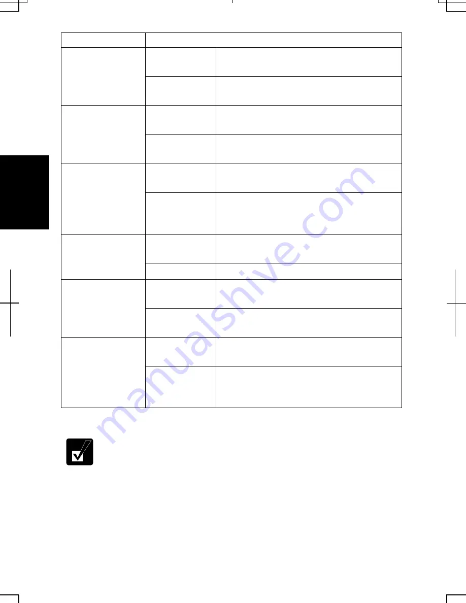
background image


3-10 


Power Scheme 

Processor Performance 

Using AC 

Power 

Always runs at highest performance state 

Home/Office Desk 

Using Battery 

Performance state will be chosen based on CPU 

demand 

Using AC 

Power 

Performance state will be chosen based on CPU 

demand 

Portable/Laptop 

Using Battery 

Performance state will be chosen based on CPU 

demand 

Using AC 

Power 

Performance state will be chosen based on CPU 

demand 

Presentation 

Using Battery 

Starts at lowest performance state; then, uses 

liner performance reduction as battery 

discharges 

Using AC 

Power 

Always runs at highest performance state 

Always On 

Using Battery 

Always runs at highest performance state 

Using AC 

Power 

Performance state will be chosen based on CPU 

demand 

Minimal Power 

Management 

Using Battery 

Performance state will be chosen based on CPU 

demand 

Using AC 

Power 

Performance state will be chosen based on CPU 

demand 

Max Battery 

Using Battery 

Starts at lowest performance state; then, uses 

liner performance reduction as battery 

discharges. 


• 

Note that Power scheme includes other power management settings 
(such as a timer for System standby, etc.) appearing on 
Power Schemes 
tab. Confirm those settings are set to an appropriate value when you 
select the processor performance using power schemes facility. 

• 

You can set your own Power scheme. Set all power management 
settings to your suitable ones, and click 
Save as…; then, type an 
appropriate name and click 
OK

Summary of Contents for Actius PC-UM30W

Page 1: ...g the equipment off and on the user is encouraged to try to correct the interference by one or more of the following measures Reorient or relocate the receiving antenna Increase the distance between the equipment and receiver Connect the equipment into an outlet on a circuit different from that to which the receiver is connected Consult the dealer or an experienced radio TV technician for help A s...

Page 2: ...in advance that temporary discontinuance of service may be required But if advance notice isn t practical the telephone company will notify the customer as soon as possible Also you will be advised of your right to file a complaint with the FCC if you believe it necessary The telephone company may make changes in its facilities equipment operations or procedures that could affect the operation of ...

Page 3: ...ce complies with part 15 of the FCC rules Operation is subject to the following conditions 1 this device may not cause harmful interference and 2 this device must accept any interference received including interference that may cause undesired operation Warning This product utilizes tin lead solder and fluorescent lamp containing a small amount of mercury Disposal of these materials may be regulat...

Page 4: ... VORSICHT UM DIE STROMZUFUHR VOLLSTÄNDIG ZU UNTERBRECHEN DEN NETZSTECKER HERAUSZIEHEN UND DIE BATTERIE ÈNTFERNEN ATTENTION POUR UN ARRET TOTAL DU SYSTEME DECONNECTEZ LA PRISE DE COURANT SECTEUR ET LA BATTERIE VARNING FÖR TOTAL ELEKTRISK URKOPPLING KOPPLA UR KONTAKTEN OCH TA UR BATTERIET PRECAUCION PARA UNA COMPLETA DESCONEXION ELECTRICA DESENCHUFE LA CLAVIJA DE LA RED Y LA BATERIA ...

Page 5: ...mely cold place to an extremely warm place A temperature difference of more than 10 C 18 F will cause condensation inside the unit which may cause damage Do not block or cover slots or openings on the cabinet These protect the computer from overheating Care should be exercised when using on heat sensitive surfaces or your lap as the base of this computer will get hot Usage Never push any objects o...

Page 6: ...ndling Never put the battery pack in a fire as it could explode and cause injury Do not attempt to open or alter the battery pack Do not place the battery where it might get hotter than 60 C 140 F Do not allow metal objects such as jewelry to short across the battery terminals as it could heat up and explode Do not allow liquids to come in contact with the battery pack Avoid dropping the pack or o...

Page 7: ...nsulated telephone wires or terminals unless the telephone line has been disconnected at the network interface Use caution when installing or modifying telephone lines Avoid using the telephone during a lightning storm There may be a remote risk of electric shock from lightning Do not use the telephone to report a gas leak while in the vicinity of the leak Wireless LAN Precautions Do not communica...

Page 8: ...ery life has expired or any other causes SHARP assumes no responsibility directly or indirectly for financial losses or claims from third persons resulting from the use of this product and any of its functions such as stolen credit card numbers the loss of or alteration of stored data etc Edition 1st Edition June 2002 Copyright 2002 SHARP Corporation This document contains or refers to proprietary...

Page 9: ...e reference please record the following information in the spaces provided below Model Number Serial Number Date of purchase Dealer s Name Place of purchase Password The serial number is printed on a sticker located on the bottom of the computer ...

Page 10: ...ldface Press Enter to continue When two or more keys are pressed simultaneously the key labels are separated by a plus sign Restart your computer by pressing Ctrl Alt Delete Sample Entries are shown in upper cases of different typeface C WINDOWS SYSTEM Words Texts on Screen such as window titles or possible parameters are italicized Double click this icon to display the Power Properties dialog box...

Page 11: ...Computer 1 7 Basic Operations Choosing Power Source 2 1 Resetting the System 2 3 Using the Glide Pad 2 4 Using the Keyboard 2 6 Sharing the Computer Windows 2000 2 8 Sharing the Computer Windows XP Professional 2 9 Battery and Power Management Battery Pack 3 1 Optional High Capacity Battery Pack 3 7 Power Management 3 8 Peripherals Using Peripherals 4 1 Using Optional External Floppy Disk Drive Un...

Page 12: ...n Modem 5 1 LAN unit 5 5 Wireless LAN 5 8 Setup Utility Running the Setup Utility 6 1 Main Menu 6 3 Advanced Menu 6 4 Security Menu 6 5 Boot Menu 6 7 Exit Menu 6 7 Appendixes Memory Module A 1 Maintenance and Care A 5 Re installation Instructions A 7 Specifications A 12 Troubleshooting Index ...

Page 13: ...appearance of your computer may be slightly different depending on the model Front A N LCD Screen 4 11 Keyboard 2 6 Glide Pad 2 4 Power Button 1 4 Status Indicators Antenna Indicator 5 8 Battery Indicator 2 1 3 3 Wireless LAN Antennas 5 8 Power Indicator 1 4 2 1 Hard Disk Caps Lock Scroll Lock Num Lock ...

Page 14: ...pansion Port 4 11 23 CF Card Slot 4 20 PC Card Slot 4 17 Audio Output Jack 4 14 4 15 Microphone Jack 4 15 Ventilation Openings v USB Ports 4 3 7 16 24 Modem Jack 5 2 LAN Jack 5 6 IEEE1394 Connector 4 25 AC Adapter Jack 1 3 CF Card Eject Switch 4 20 22 Security Slot A 5 ...

Page 15: ...uickly as possible Read this chapter first Installing Battery Pack Your computer is powered with either the rechargeable battery pack or AC power See the next chapter for more information on power sources Before using the computer for the first time 1 Place the computer upside down 2 Slide the battery stopper on the battery pack to the unlocked position Battery Stopper ...

Page 16: ...the notched parts of the battery to the projected parts on the computer then push the battery pack until you hear the clicking sound 4 Slide the battery stopper to the locked position 5 Turn over your computer and go to the next section Notched Part Projected Part ...

Page 17: ...er AC adapters may damage the computer Always hold the AC power cord by its plug when removing it from the wall outlet Never pull on the cord When using the computer for the first time be sure to connect it to AC power If using the battery instead you may not be able to complete the Windows setup if the battery does not have enough power 4 Slide the display cover lock lever to the left until the d...

Page 18: ...ore than 90 degrees to raise the keyboard completely Otherwise the keyboard or the computer may malfunction 6 Press the power button to turn on your computer When you turn on the computer the power indicator turns green the computer goes through a self test to detect any problems and Windows setup process starts See the next page Power Indicator Keyboard Power Button ...

Page 19: ...eps are Configuring your location language and keyboard Configuring your time zone Accepting license agreement Naming your computer Creating an account Completing configuration To setup Windows follow the instructions on the screen See also the Windows manual It takes approximately 15 20 minutes to complete the entire setup process Do not turn off the computer until completing Windows setup If you...

Page 20: ...can send commands to Windows or other application programs To open the properties dialog boxes click the Start button to open the Start menu then select Settings Control Panel and double click the XXX icon Some of the dialog boxes you will use often are Display Phone and Modem Options Mouse Power Options System Properties Dialog Box in Windows XP Professional In this manual you will often see the ...

Page 21: ... Down 2 In the Shut Down Windows dialog box select Shut down from the pull down menu and click OK From the start menu Windows XP Professional 1 Click start Turn Off Computer 2 In the Turn off computer dialog box click Turn Off Close the cover to keep the screen and keyboard clean and protected If you have not saved a file a dialog box will appear asking whether you want to save it Do not turn off ...

Page 22: ...1 8 1 ...

Page 23: ...rd battery You can also use an optional battery See Chapter 3 for battery information About the Power Indicators The following indicators show the power status of your computer Indicator Light Meaning On green Operating Blinking green In System Standby Power Off Powered off or in System Hibernate On green Fully charged On orange Being charged When Connected to AC Power Blinking orange In abnormal ...

Page 24: ... AC adapter provides power for operation and charges the battery The AC input voltage can range from 100 to 240 volts so that you can use the computer with the appropriate plug adapter The AC power cord included with the computer is appropriate for the voltage used in the area in which you purchased your computer If you attempt to connect the computer to a wall outlet other than in this area check...

Page 25: ...rl Alt Del keys simultaneously and follow the instructions on the screen Resetting may cause data loss Use the resetting process only if the normal Windows Shut Down does not work because of software malfunction Although resetting will not damage the system you may lose the data you are processing Power Switch You can turn off the computer with the power button if you encounter hardware or softwar...

Page 26: ...rectly Using the Glide Pad Take a moment to become familiar with how the glide pad works Place Your Fingertip Place your left or right hand next to the glide pad resting your wrist naturally in a relaxed manner Place your thumb or finger on the glide pad Move Your Fingertip The rectangular pad of the glide pad acts like a miniature duplicate of the display As you slide your fingertip across the pa...

Page 27: ...utton when the object reaches its destination Or you can tap the pad twice instead of pressing the left button in step 2 Scroll You can scroll through information in a list or in a document by using the glide pad To view information vertically place your finger on the most right part of the glide pad and slide your finger up and down To view horizontally place your finger on the bottom part of the...

Page 28: ...function 90 Special Keys Windows Key Opens the Windows Start menu Application Key Opens an application specific short cut menu equivalent to right clicking System Function Keys When pressed together with the Fn key function keys set specific system parameters This combination is sometimes referred to as hot keys Fn F1 Turns the wireless LAN antenna on and off This combination functions when Wirele...

Page 29: ...creases the LCD screen brightness Fn F7 Increases the LCD screen brightness Fn F11 Turns the LCD screen on and off Fn F12 Forces the computer into System standby See Power Management of Chapter 3 for more information ...

Page 30: ...s level and click Finish 8 Click OK to close the dialog box 9 Close the Control Panel window Changing User Name 1 Follow the steps 1 to 3 of the above 2 In Users and Passwords dialog box check Users must enter a user name and password to use this computer then double click the user name you want to change 3 Change the name and click OK twice 4 If Windows requires click Yes then type the user name ...

Page 31: ...h person Every user can choose their favorite desktop setting web site lists or make their own My Documents folder etc and save them to their user accounts When you turn on the computer select your user account Set a New User Account 1 Click start Control Panel 2 Click User Accounts If Classic view is selected double click User Accounts icon 3 Click Create a new account 4 Type a name for the new a...

Page 32: ...data may appear 3 Select a new account to start Windows XP again If you cannot see Switch User in Log Off Windows dialog box click Change the way users log on or off in User Accounts dialog box and check Use Fast User Switching and click Apply Options Set Password to User Account You can set a password to each user account to avoid unauthorized use of your computer Once you set the password you ne...

Page 33: ...to the next step You cannot change the password of another user account 3 Select Change the password or Change my password If the password has not been set yet Change the password or Change my password will not appear Only the members of the Computer administrators group can change the password of another user account 4 Type a new password 5 Type the new password again to confirm it 6 If necessary...

Page 34: ...members of the Computer administrators group can delete the password of another user account 4 Type your password and click Remove Password If you log on to the computer as a member of the Computer administrators group and want to delete the password of another user account just click Remove Password 5 Close User Accounts dialog box then the Control Panel window ...

Page 35: ...ormance and Maintenance Power Options in Category view or double click Power Options icon in Classic view Battery Pack When not connected to an external power source your computer operates with the rechargeable battery pack The duration of the battery life may be longer if the computer s Power Management is active See the next section for power management To keep the battery life long Condition se...

Page 36: ...ill turn on again The battery pack may not be installed correctly if the battery indicator blinks orange In this case turn off the computer remove the AC adapter and the battery pack then install the battery pack and connect the AC adapter again If the battery indicator still blinks orange ask your local dealer for assistance When the battery pack is hot for example after a long usage it may take ...

Page 37: ...herwise the computer will be shut down and the data may be lost In Windows the alarm will tell you when the battery drops to the specified level by sounding an alarm or displaying a message and let your computer go on System standby hibernate or be shut down automatically 1 In the Power Options Properties dialog box select Alarms tab 2 Set the battery level at which the alarms are activated We rec...

Page 38: ...utomatically 5 Connect the computer to AC power and let the battery fully charge again 6 Turn on the computer and follow the steps 3 to 5 again 7 Restart the computer The conditioning process is complete Do not connect the computer to wall outlet while discharging the battery The conditioning will be cancelled Changing the Battery Pack The capacity of a battery pack gradually decreases when used r...

Page 39: ...ttery release lever to the unlocked position and hold it then pull out the battery pack 5 Lift up the battery pack and remove it from the computer 6 Slide the battery stopper of a new battery pack to the unlocked position Battery Stopper Battery Release Lever Battery Stopper ...

Page 40: ...ng the notched parts of the battery to the projected parts of the computer then push the battery pack until you hear the clicking sound 8 Slide the battery stopper to the locked position 9 Turn over the computer and it s ready to use Notched Part Projected Part ...

Page 41: ...Connecting High Capacity Battery Pack Follow the steps in Changing the battery pack in this chapter Charging High Capacity Battery Pack Follow the steps in Charging the battery pack in this chapter Checking the Battery Level of High Capacity Battery Pack Follow the steps in Checking the Battery Level in this chapter Conditioning the High Capacity Battery Pack Follow the steps in Conditioning the b...

Page 42: ... Power Options If Classic view is selected double click Power Options icon for Windows XP Professional Note that the power management may not seem to function when you are using an application program that accesses the hard disk periodically Stopping Power Supply to the Hard Disk 1 In the Power Options Properties dialog box select Power Schemes tab 2 Set Turn off hard disks to an appropriate value...

Page 43: ...the icon or selecting Intel R SpeedStep TM technology tab in Power Options Properties dialog box Controlling CPU Speed Windows XP Professional Windows XP Professional will control the processor performance to reduce power consumption Do not control the processor performance or connect disconnect the AC adapter while communicating or reading writing data Otherwise the computer may malfunction 1 In ...

Page 44: ...y Always runs at highest performance state Using AC Power Performance state will be chosen based on CPU demand Minimal Power Management Using Battery Performance state will be chosen based on CPU demand Using AC Power Performance state will be chosen based on CPU demand Max Battery Using Battery Starts at lowest performance state then uses liner performance reduction as battery discharges Note tha...

Page 45: ...ves the current condition of the computer in an area of the hard disk and turns off the computer Your system enters and resumes from System hibernate per the conditions mentioned later In System hibernate the power indicator or the battery power indicator turns off To resume from System hibernate press the power button When entering resuming from System standby hibernate follow the instructions be...

Page 46: ... hibernate automatically when the specified time has passed without any operation To set the time 1 In the Power Options Properties dialog box select Power Schemes tab 2 Set the time after which the computer will enter System standby hibernate in System standby or System hibernates 3 Click OK 4 Close the Control Panel window Entering System Standby Hibernate Your computer enters System standby hib...

Page 47: ...K 4 Close the Control Panel window You press Fn F12 The above functions if you perform the following 1 In the Power Options Properties dialog box select Advanced tab 2 Select Hibernate or Stand by in When I press the sleep button on my computer 3 Click OK 4 Close the Control Panel window If Ask me what to do is selected in the step 2 of You press the power button or You press Fn F12 the Turn off c...

Page 48: ...wer Management 1 In the Power Options Properties dialog box select Power Schemes tab 2 Set Turn off monitor Turn off hard disks System standby and System hibernates to Never then click OK 3 Close the Control Panel window ...

Page 49: ... shown on the next page For the details refer to the section explaining each device or contact your dealer Be sure to turn off the computer and the peripheral devices before connecting them except when connecting USB devices an IEEE 1394 device or inserting a PC card or a CF card Confirm the peripheral device you will connect is Windows 2000 or Windows XP Professional compatible Some devices have ...

Page 50: ...ion Overview Including the optional external floppy disk drive unit CE FD04 05 and the provided external CD ROM drive unit CE CD05 Headphone Audio Equipment USB Device PC Card Microphone CF Card IEEE 1394 Device Expansion Port ...

Page 51: ... to malfunction Connect the floppy disk drive unit cable to either of the USB ports on the right side of the computer Be sure to let the USB mark side up when connecting the cable to the computer CE FD04 is required to connect the included USB cable to the drive first Handling Floppy Disks Do not open the shutter and touch the disk inside otherwise you will not be able to read or write data to the...

Page 52: ...ot use excessive force when inserting the floppy disk If you have difficulty inserting or removing disks seek the assistance of an authorized service technician Do not touch the disk while reading writing data It may cause malfunction of the computer and the drive Removing Before removing the floppy disk make sure the indicator of the floppy disk drive unit is not lit Press the eject button firmly...

Page 53: ...y stored on the disk is lost You cannot format a double density 2DD 720KB floppy disk for Windows XP Professional only Removing Optional External Floppy Disk Drive Unit To remove the unit you need to perform the following steps before you remove it In Windows 2000 1 Click Unplug or Eject Hardware icon on the taskbar 2 Click Stop Mitsumi USB Floppy Drive A 3 Click OK in Safe To Remove Hardware dial...

Page 54: ...use electrical shock hazard or a laser may damage your eyes Do not store or use the CD ROM drive unit in a dusty humid oily environment or under damp or moist conditions Do not turn up the volume too high when using the headphones Do not leave the CD ROM drive unit in direct sunlight near a heat source or especially in a hot automobile Do not drop or jar the CD ROM drive unit Do not touch the pins...

Page 55: ... ROM drive unit It may cause the drive to malfunction 1 Connect the core side connector of the included USB cable to the cable connector of the drive unit 2 Insert the USB connector of the cable into one of the USB ports of the computer The CD ROM drive unit automatically turns on and the power indicator lights up 3 Slide the cover latch to the right and open the cover USB Ports Power Indicator Ca...

Page 56: ...on the CDs cause noise or improper tracking If a CD is dirty or does not play properly clean it with a soft dry cloth wiping straight out from the center along the radius Inserting a CD You can operate the external CD ROM drive unit only when the computer is on 1 Make sure the busy indicator light is not on 2 Slide the cover latch to the right to open the cover and raise it 3 Place your CD onto th...

Page 57: ...gently wipe the lens Removing a CD 1 Make sure the busy indicator is not lit 2 Slide the cover latch to the right and open the cover 3 Press down the disk spindle and remove the CD from the tray holding its edge Make sure the busy indicator is not lit or blinking before opening the disk cover When opening the cover if the CD is still spinning wait until it has stopped then remove it Playing a CD W...

Page 58: ... Safely remove USB Mass Storage Device then Safe To Remove Hardware dialog appears 3 Remove the USB cable from the computer Mode Switches There are the mode switches on the bottom of the CD ROM unit These switches are for technical services Keep them as a default setting OFF Cleaning External CD ROM Drive Unit Do not use solvents such as benzine thinner alcohol record cleaner or anti static spray ...

Page 59: ...ble CE PB02 to connect an external monitor with your computer 1 Turn off the computer and the external monitor 2 Connect the provided parallel VGA converter cable with the display cable as shown below If the display cable has screws make sure to tighten them 3 Open the cover of the expansion port on the left side of your computer 4 Connect the parallel VGA converter cable to the expansion port the...

Page 60: ...hen click Advanced button 2 Select Intel Graphic Technology tab then click Graphics Properties 3 Select the output display and click OK 4 Click OK three times and close the Control Panel window You can also switch the display with Fn F5 While playing video or animation you may not be able to switch the display The screen may be distorted when you switch the display In this case refresh the screen ...

Page 61: ...rts move mouse pointer to the parts and scroll it To set 1280 x 1024 1400 x 1050 and 1600 x 1200 resolution mode selectable open the Display Properties dialog box click Settings tab Advanced button and uncheck Hide modes that this monitor cannot display of Monitor tab 3 On the internal LCD screen the number of colors in this mode is made using a Dithering algorithm You cannot switch to a display r...

Page 62: ...o speakers with an amplifier or an audio equipment to the audio output jack on the right side of the computer You can adjust the output volume in Windows by double clicking the speaker icon on the taskbar or use Fn F3 or F4 keys combination White Red LINE IN R LINE IN L Audio Output Jack Audio Output Jack Speakers with an Amplifier ...

Page 63: ...one jack Use an electret condenser microphone with an impedance of 2 2kΩ and an allowable voltage of 2V To record sound 1 Click Start then point Programs Accessories Entertainment for Windows 2000 or click start then point All Programs Accessories Entertainment for Windows XP Professional 2 Click Sound Recorder 3 See Help for Sound Recorder for more information Audio Output Jack Microphone Jack ...

Page 64: ...rrectly you will see the message on the screen In this case install the driver by following the instructions on the screen To remove USB devices you may need to perform the following instructions before you remove them In Windows 2000 1 Click Unplug or Eject Hardware icon on the taskbar 2 Click Stop xxxxx xxxxx is the name of your USB device 3 Click OK then remove the device from the computer In W...

Page 65: ...to its manual Inserting PC Card When a new card is correctly inserted the appropriate driver is automatically installed If the driver is not installed correctly you will see the message on the screen In this case install the PC card driver by following the instructions on the screen 1 Confirm the PC card eject button is inside the computer cabinet 2 Push the PC card eject button so that it pops ou...

Page 66: ...he label face up until it locks into place Ejecting PC Card Some PC cards may become hot after long use Be sure to use the procedure below when ejecting a PC card Otherwise the system may not work properly In Windows 2000 1 Click Unplug or Eject Hardware icon on the taskbar 2 Click Stop xxxxx xxxxx is the name of your PC card 3 Click OK and go to Ejecting PC card on the next page Label Face Up ...

Page 67: ...dialog appears Go to Ejecting PC card below Ejecting PC Card 1 Push the PC card eject button so that it pops out from the side of the computer 2 Push the eject button so that the PC card pops out then remove it 3 Push the PC card eject button all the way inside the cabinet for safekeeping 4 Insert the protection card Be sure to insert the protection card after you finish using the PC card to prote...

Page 68: ... manual Inserting CF Card When a new card is correctly inserted the appropriate driver is automatically installed If the driver is not installed correctly you will see the message on the screen In this case install the CF card driver by following the instructions on the screen 1 Lift up the front of the computer 2 Slide the CF card eject switch inward which is on the bottom of the computer and rem...

Page 69: ...2000 1 Click Unplug or Eject Hardware icon on the taskbar 2 Click Stop xxxxx xxxxx is the name of your CF card 3 Click OK and go to Ejecting CF card on the next page In Windows XP Professional 1 Click Safely Remove Hardware icon on the taskbar If you cannot find the icon click to show all kinds of icons 2 Click Safely remove xxxx xxxxx is the name of your CF card then Safe To Remove Hardware dialo...

Page 70: ...he CF card eject switch inward which is on the bottom of the computer and remove the CF card 3 Insert the protection card Be sure to insert the protection card after you finish using the CF card to protect the CF card slot from being damaged Protection Card Eject Switch ...

Page 71: ...the computer and the printer 2 Connect the provided parallel VGA converter cable with the printer cable If the printer cable has screws make sure to tighten them 3 Open the cover for the expansion port on the left side of the computer then connect the parallel VGA converter cable to the expansion port and the other end of the printer cable to the printer Parallel VGA Converter Cable CE PB02 Printe...

Page 72: ...nnect the parallel cable from the port Connecting to USB Port Be sure to read the printer manual before connecting the USB printer to the computer Some printer may not use New Hardware Find wizard to install the printer driver You can connect the USB printer to the computer without turning off the computer Printer Cable USB Ports ...

Page 73: ...1394 device you will connect is Windows 2000 or Windows XP Professional compatible Some IEEE 1394 devices require that you install drivers before use Use AC power for the computer especially when reading writing the data Connecting IEEE 1394 Device Attach the provided core to the DV IEEE1394 cable to insure compliance with requirements of EMC regulations for computing equipment You need not turn o...

Page 74: ...dware icon on the taskbar 2 Click Stop xxxxx xxxxx is the name of your IEEE 1394 device 3 Click OK then remove the DV cable from the computer In Windows XP Professional 1 Click the Safely Remove Hardware icon on the taskbar If you cannot find the icon click to show all kinds of icon If the icon does not appear go to Step 3 2 If the name of your device appears click Safely remove xxxxx xxxx is the ...

Page 75: ...nected to a digital ISDN terminal or a digital PBX Use TA terminal adapter to connect the built in modem to a digital telephone line If an unusual device is attached to the line you are connecting to the modem may not function properly Remove the device or contact the dealer of the device Before connecting to a PBX consult the PBX maintenance staff or its service company If the electric characteri...

Page 76: ...e modem jack Do not insert the modem cable into the LAN jack It may damage the LAN jack or the modem cable 4 Connect the other end of the modem cable to the telephone line 5 Turn on the computer Connect the modem to the telephone line directly Do not use a distributor or allotter Configuring the Modem in Windows 2000 Make the necessary adjustments as shown below 1 From the Start menu select Settin...

Page 77: ...the Windows desktop double click My Computer icon 2 Click Network and Dial up Connections 3 Double click Make New Connection 4 Follow the instruction of the Network Connection Wizard dialog box to create a new account Hyper Terminal and Phone Dialer You can find these applications by opening the Start menu and selecting Programs Accessories Communications HyperTerminal lets you connect to other co...

Page 78: ...selected double click Network Connections icon In Network Connections dialog box click Create a new connection of Network Tasks When the New Connection Wizard dialog box appears follow the instructions on the screen If you plan on connecting to the Internet by using the modem to dial an Internet Service Provider ISP have your account information and dial up number ready before you begin the wizard...

Page 79: ...necting to 100 BASE TX LAN Connect your computer to LAN 1 Turn off the computer 2 If your computer is provided with the LAN cable go to the step 4 If with the core for a LAN cable go to the next step 3 Attach the provided core to one end of your LAN cable Insert the cable into the core and close the core until it clicks 4 Open the cover for the LAN jack on the right side of your computer To avoid ...

Page 80: ...log box set the fields according to your network status Refer to your network administrator Attach the provided core to your LAN cable to insure compliance with requirements of EMC regulations for computing equipment If your computer is provided with a LAN cable always use that LAN cable If your LAN cable has no core attached please attach the provided core before use Make sure to log on the compu...

Page 81: ... Attach the provided core to your LAN cable to insure compliance with requirements of EMC regulations for computing equipment If your computer is provided with a LAN cable always use that LAN cable If your LAN cable has no core attached please attach the provided core before use Make sure to log on the computer as a member of the Computer administrators group Otherwise you cannot set or change som...

Page 82: ... of computers each equipped with wireless networking interface Each computer can communicate directly with other wireless enabled computers The range to give reliable performance and the quality of connection vary depending on the environment where you perform To communicate with the wireless LAN activate the integrated antennas with the following steps Activate Antennas You can enable disable the...

Page 83: ... Protocol TCP IP in Components checked are used by this connection 4 Select Use the following IP address in Internet Protocol TCP IP Properties dialog box and set a unique IP address to 192 168 1 2 through 192 168 1 254 and the Subnet mask to 255 255 255 0 then click OK The IP address of each computer should be unique The Default gateway can be blank 5 Click OK and Close then close the Network and...

Page 84: ... cannot set or change some settings for wireless LAN 1 Click start Control Panel 2 Click Network and Internet Connections Network Connections If Classic view is selected click Network Connections 3 Select Wireless Network Connection then click Change settings of this connection of Network Tasks 4 Double click Internet Protocol TCP IP in This connection uses the following items 5 In Internet Protoc...

Page 85: ...ireless LAN 1 Click icon on the taskbar Wireless LAN Card Utility for Windows dialog box opens A connected network name appears in ESSID of Connected with AP Information of Card Status tab if available If you cannot find the icon click Start Programs SHARP Wireless LAN Configuration Utility for members of the Administrators group Clicking Rescan button detects another available network When the WE...

Page 86: ...ced tab then Refresh button of Available networks in Wireless Network Connection Properties dialog box then click OK When the WEP security of the wireless network that you want to access is enabled make sure to enter the Network key and select Key format and Key length correctly Click Add button in Wireless Networks tab of Wireless Network Connection Properties dialog box 3 Click Wireless Network ...

Page 87: ...aved in a special area called CMOS RAM which the system reads every time you turn on the computer Your computer is shipped from the factory with the appropriate setting of the Setup Utility Leave it as default in normal use Contents of the Setup Utility The Setup Utility consists of four menu pages as follows Main Configures basic setting Advanced Configures device interface I O ports etc Security...

Page 88: ...the item Minus or Space key Changes the value In the item with mark press Enter to open a sub menu Press Esc to close the sub menu and return to the previous menu 4 Select Exit 5 Select one of the exit methods and press Enter 6 Confirm the message and press Enter again The system restarts When the Setup Utility is opened power management does not work Do not close the display cover ...

Page 89: ...setting An external keyboard will be numlocked if connected C3 State defines whether the system reduces power consumption while the CPU is idling USB Key Mouse Emulation defines whether USB devices can be used in MS DOS mode Quick Boot defines whether the system skips the check of the internal memory while booting to shorten the boot time Quiet Boot defines whether the SHARP logo appears on the sc...

Page 90: ...e can be selected Bi directional ECP Extended Capabilities Port mode EPP Enhanced Parallel Port mode or Output only Disabled means that you cannot use the port Internal Pointing Device enables or disables the built in glide pad System Beep controls the volume level of the beep before Windows starts Resolution Expansion defines whether the screen is expanded when the resolution is 640x480 or 800x60...

Page 91: ...re set to Normal Device Configuration enables and disables built in devices such as USB Audio system modem LAN PC card IEEE1394 and wireless LAN Supervisor and User Password Setting a password will protect your computer against unauthorized access Once a password is set the system requires the password when entering to the Setup Utility And if Password on boot is enabled the system will require a ...

Page 92: ...rd 1 In the Security menu of the Setup Utility select Set Supervisor Password or Set User Password and press Enter 2 Type your current password and press Enter 3 Type your new password and press Enter 4 Type your new password again and press Enter twice 5 Select Exit menu and confirm Exit Saving Changes is highlighted then press Enter 6 Confirm Yes is highlighted and press Enter The system restart...

Page 93: ...SB floppy disk drive LAN Boot defines whether the system boots from other server via the LAN unit of the computer Exit Menu Exit Saving Changes saves the settings you have changed and exits the Setup Utility Exit Discarding Changes exits the Setup Utility without saving the settings you have changed Load Setup Defaults returns the values of all items to the default To exit select one of the above ...

Page 94: ...6 8 6 ...

Page 95: ...ling the memory module carefully discharge static electricity from your body by touching an unpainted metal area Avoid touching the integrated circuits on a memory module Handle all components by the edges Keep the memory module in the anti static wrapping until you are ready to install it 1 Turn off the computer and disconnect the AC adapter and remove the battery pack and peripheral devices See ...

Page 96: ...en the display cover and insert the provided memory upgrade tool into the small hole of the glide pad 3 Pull up the memory upgrade tool The glide pad is lift up slightly 4 Open the glide pad Glide Pad Memory Upgrade Tool ...

Page 97: ...odule is set correctly 6 Press the memory module softly into the memory socket matching the notched parts of the module with the projected parts of the socket until you hear the clicking sound When you cannot insert the memory module properly try to bend the both latches of the slot outward and press down the module into place Projected Part Notched Part 20 Projected Part Notched Parts Latch Memor...

Page 98: ...he computer and check the memory size In Windows 2000 Click Start Settings Control Panel Double click System icon then select General tab In Windows XP Professional Click start My computer View system information of System Tasks Your memory size appears at the bottom of the sentence Share video memory size will not be included with the value Uninstalling the Memory Module 1 Follow steps 1 4 of Ins...

Page 99: ...y cable into the security slot on the right side of your computer to prevent theft Cleaning the Computer Cabinet Apply a small amount of mild cleaning solution to a dry lint free cloth and wipe the cabinet with the cloth Never clean the computer while it is powered on Do not use alcohol benzene thinner or other strong chemical agents that may damage the cabinet Security Cable Security Slot ...

Page 100: ...uidelines Before traveling back up your data on floppy disks or other external media Do not travel with any peripheral devices connected such as an optional external floppy disk drive unit or the provided external CD ROM drive and also the parallel VGA converter cable connected Do not carry the computer powered on This may result in loss of data and or damage to the hard disk drive Make sure the d...

Page 101: ... for disaster recovery purposes The Software is only authorized for distribution together with a specific computer This License authorizes you to use the Software for disaster recovery purposes only to restore the hard disk image contained on the CD to the computer with which the CD and Software were originally shipped 3 NONPERMITTED USES Without the express permission of PowerQuest you may not a ...

Page 102: ...F BUSINESS INFORMATION OR OTHER PECUNIARY LOSS EVEN IF POWERQUEST CORPORATION HAS BEEN ADVISED OF THE POSSIBILITY OF SUCH DAMAGES WHETHER SUCH LIABILITY IS BASED ON CONTRACT TORT WARRANTY OR ANY OTHER LEGAL OR EQUITABLE GROUNDS BECAUSE SOME STATES DO NOT ALLOW THE EXCLUSION OR LIMITATION OF LIABILITY FOR CONSEQUENTIAL OR INCIDENTAL DAMAGES THE ABOVE LIMITATION MAY NOT APPLY TO YOU 8 NO WAIVER Any ...

Page 103: ...he data Before formatting the hard disk you should back up your data For details on how to back up your data see the Windows Online Help Selecting the way to recover your system Your computer has two drives C and D when it was shipped from the factory You can select the way to recover your system Recovers C drive only Recommended This process will format C drive only and recover C drive to the sam...

Page 104: ... the Main menu set CD ROM Drive to the top of the list then press ESC 8 In the Exit menu confirm Exit Saving Changes is highlighted and press Enter twice 9 Read the message on the screen and select the operating system that you had selected for the first time you use the computer then press Enter You cannot change the operating system from the first choice 10 Read the message on the screen and sel...

Page 105: ... message The Operating System has been recovered successfully remove the Product Recovery CD ROM disk 3 The system will restart automatically 16 When the message Press F2 to enter SETUP appears press F2 The Setup Utility opens 17 In the Exit menu select Load Setup Defaults then press Enter twice 18 In the Exit menu confirm Exit Saving Changes is highlighted and press Enter twice The system restart...

Page 106: ...nal microphone jack monaural Others USB port x 2 IEEE 1394 connector expansion port for Parallel VGA converter cable Modem Data 56Kbps receive 33 6Kbps send Fax 14 4Kbps LAN 100 BASE TX 10 BASE T LAN Radio Technology DSSS IEEE802 11b compliant Frequency Band 2400 2483 5MHz Operating Channels 11 channels Wireless LAN Data Rate 1 2 5 5 11 Mbps Power AC adapter 100 240V 50 60 Hz Battery Rechargeable ...

Page 107: ...Appendixes A 13 Options may not be available in some countries Standard Battery Pack CE BL17 High Capacity Battery Pack CE BL18 External Floppy Disk Drive CE FD04 CE FD05 AC Adapter CE MU01V ...

Page 108: ...A 14 Appendixes ...

Page 109: ...rs and error messages If you encounter a software error try to determine if the error message is from your operating system or from an application program and refer to the appropriate manual for possible remedies You can also refer to the Windows manual or Windows Help program to solve the problem To access the Help program click Start Help for Windows 2000 or start Help and Support Windows XP Pro...

Page 110: ...tional external floppy disk drive unit either a defective disk or one without an installed operating system Remove the disk Question Why can t I boot from the floppy disk Make sure that the optional external floppy disk drive unit is correctly connected to the computer Check whether the floppy disk set to the optional external floppy disk drive unit contains a system disk Check whether Floppy Disk...

Page 111: ...eyboard or the glide pad function Question Why does the external monitor display nothing or the image on it distorted Confirm the monitor is turned on Confirm the monitor is connected correctly Make sure an external monitor is selected as the display by pressing Fn F5 If you use Fn F5 to change the display the image may be distorted Press Fn F5 again to return the previous display and use Display ...

Page 112: ... cannot turn off the system with the power switch press the reset switch on the bottom of your computer to turn off the system refer to page 2 3 Ten seconds later turn on the computer by pressing the power switch Question Why does the glide pad malfunction The pad of the glide pad or your palm may be moist or dirty and grease Wipe the glide pad with a soft dry cloth Trouble with Floppy Disks Quest...

Page 113: ...Trouble with Communication Question Why can t I communicate through the built in modem Confirm the telephone line is properly connected to the modem jack Confirm the dial setting pulse or tone of Windows or communication software is matched with the telephone line Confirm the country region setting is appropriate Confirm the network configuration is appropriate Confirm the user name or password is...

Page 114: ...for Windows XP Professional Accessories Command Prompt 2 Type ipconfig all then press Enter The information about IP appears 3 For the LAN see the numbers of Physical Address in Ethernet adapter Local Area Connection section For the Wireless LAN see the numbers of Physical Address in Ethernet adapter Local Area Connection 2 section for Windows 2000 or Ethernet adapter Wireless Network Connection s...

Page 115: ...Other Places then View network connections in Network Tasks Network Connections dialog box appears 3 Right click Wireless Network Connection then click Disable 4 Right click Wireless Network Connection then click Enable When you have more than one available access points your computer may be connected to other than right one you want to access 1 Right click icon on the taskbar then click View Avai...

Page 116: ... 5 10 Adjust the distance between the computers by bringing your computer closer to others and remove any obstructions that may impede the communication then try to connect again The distance between computers or access points should be less than approximately 60 m 190 feet in the direct line of sight Confirm the IP address and the subnet mask of each computer are set correctly Confirm the WEP key...

Page 117: ...r is installed From the Start menu select Settings Printers to confirm your printer is installed there If not double click Add Printer to install your printer for Windows 2000 From the start menu select Printers and Faxes to confirm your printer is installed there If not click Add a printer of Printer Tasks to install your printer for Windows XP Professional See also the Windows Help Question Why ...

Page 118: ...ng procedure Windows 2000 1 From the Start menu select Settings Control Panel 2 Double click System icon 3 Click Hardware tab then Device Manager 4 Double click the device you cannot use 5 Confirm Use this device enable appears in Device usage Windows XP Professional 1 Click start Control Panel 2 Click Performance and Maintenance then System If Category view is selected double click System icon 3 ...

Page 119: ...ding area or the front of the keyboard may become hot but this is not a problem Question Why can t I record the sound from the microphone Follow the instructions below 1 Double click the speaker icon on the taskbar 2 Click Options and select Properties 3 Select Recording in Adjust volume for then click OK 4 Confirm Select is checked in Microphone of Recording Control dialog box 5 Close the Recordi...

Page 120: ...Troubleshooting T 12 ...

Page 121: ...ng 4 8 inserting 4 8 playing 4 9 removing 4 9 CF Cards ejecting 4 21 inserting 4 20 D Display changing brightness 2 7 changing number of colors 4 12 changing resolution 4 12 switching the display 2 6 4 12 troubleshooting T 3 turning off 2 7 E External monitor connecting 4 11 disconnecting 4 12 switching the display 2 6 4 12 F Floppy disk formatting 4 5 handling 4 3 inserting 4 4 removing 4 4 Flopp...

Page 122: ...quipment 4 14 CF card 4 20 connecting guidelines 4 1 external CD ROM drive 4 6 external floppy disk drive 4 3 external monitor 4 11 headphones 4 15 IEEE 1394 device 4 25 microphone 4 15 parallel VGA converter cable 4 11 23 PC cards 4 17 printer 4 23 troubleshooting T 9 USB device 4 16 Power choosing AC or battery 2 1 indicator 1 4 2 1 Power management controlling CPU speed 3 9 disabling 3 14 stopp...

Page 123: ...munications T 5 display T 3 floppy disk drive T 4 hard disk drive T 5 keyboard or glide pad T 4 peripherals T 9 reference T 1 U USB device 4 16 W Windows 2000 changing user name 2 8 changing user password 2 8 first time setup 1 5 properties dialog boxes 1 6 registering user 2 8 Windows XP Professional changing a password 2 11 deleting a password 2 11 first time setup 1 5 properties dialog boxes 1 ...

Page 124: ...Index 2 Index ...

Reviews: