Tools & Setup
44
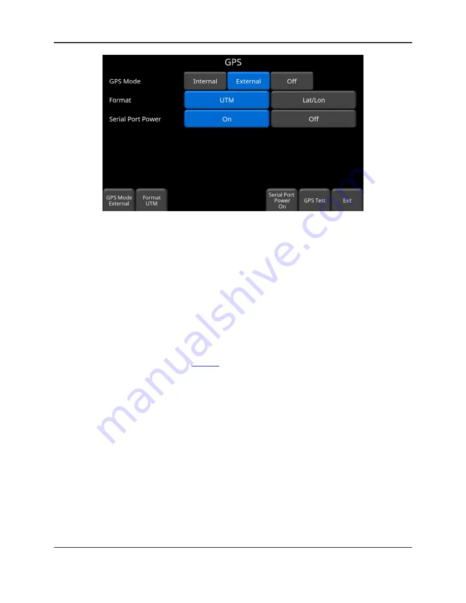
Figure 4-23: GPS Setup screen
The following buttons are explained below:
o
GPS Mode
–you can select whether to use the internal GPS, external GPS or no GPS at
all (Off)
o
Format
– GPS units can be either UTM (Universal Transverse Mercator) or
Latitude/Longitude coordinates
o
GPS Test
– pressing this will return to the screen in Figure 4-21
o
Serial Port Power -
the serial port on the back of the Display Unit can output power,
thereby enabling a single cable to be used for the GPS (power and data). When you
purchase the GPS from Sensors & Software, this cable is included. However, if you use
a 3
rd
party GPS, you need to determine if the GPS can accept power via the serial port.
Check the pin-out diagram in
Pressing the
On
button will turn power to the serial port on, but it will display a warning
message first Figure 4-24. Press
Off
to disable power to the serial port.
Summary of Contents for LMX200 Series
Page 1: ...2015 00158 09 ...
Page 2: ...ii ...
Page 4: ...Product Registration iv ...
Page 10: ...x ...
Page 14: ...xiv ...
Page 48: ...Tools Setup 48 ...
Page 52: ...GPR Concepts 52 ...
Page 86: ...SliceView 86 ...
Page 96: ...Capturing Screens E mailing Mini Reports 96 Figure 10 3 Example of a Mini Report ...
Page 104: ...Transferring Data to a PC 104 ...
Page 108: ...Troubleshooting 108 ...
Page 111: ...Care Maintenance 111 ...
Page 112: ...Care Maintenance 112 ...
Page 114: ...Parts List Accessories 114 ...
Page 116: ...Parts List Accessories 116 ...
Page 118: ...Technical Specifications 118 ...
Page 120: ...Appendix A Health Safety Certification 120 ...
Page 128: ...Appendix B GPR Emissions Interference and Regulations 128 ...
Page 130: ...Appendix C Instrument Interference 130 ...
Page 132: ...Appendix D Safety around Explosive Devices 132 ...


