Line Scan
58
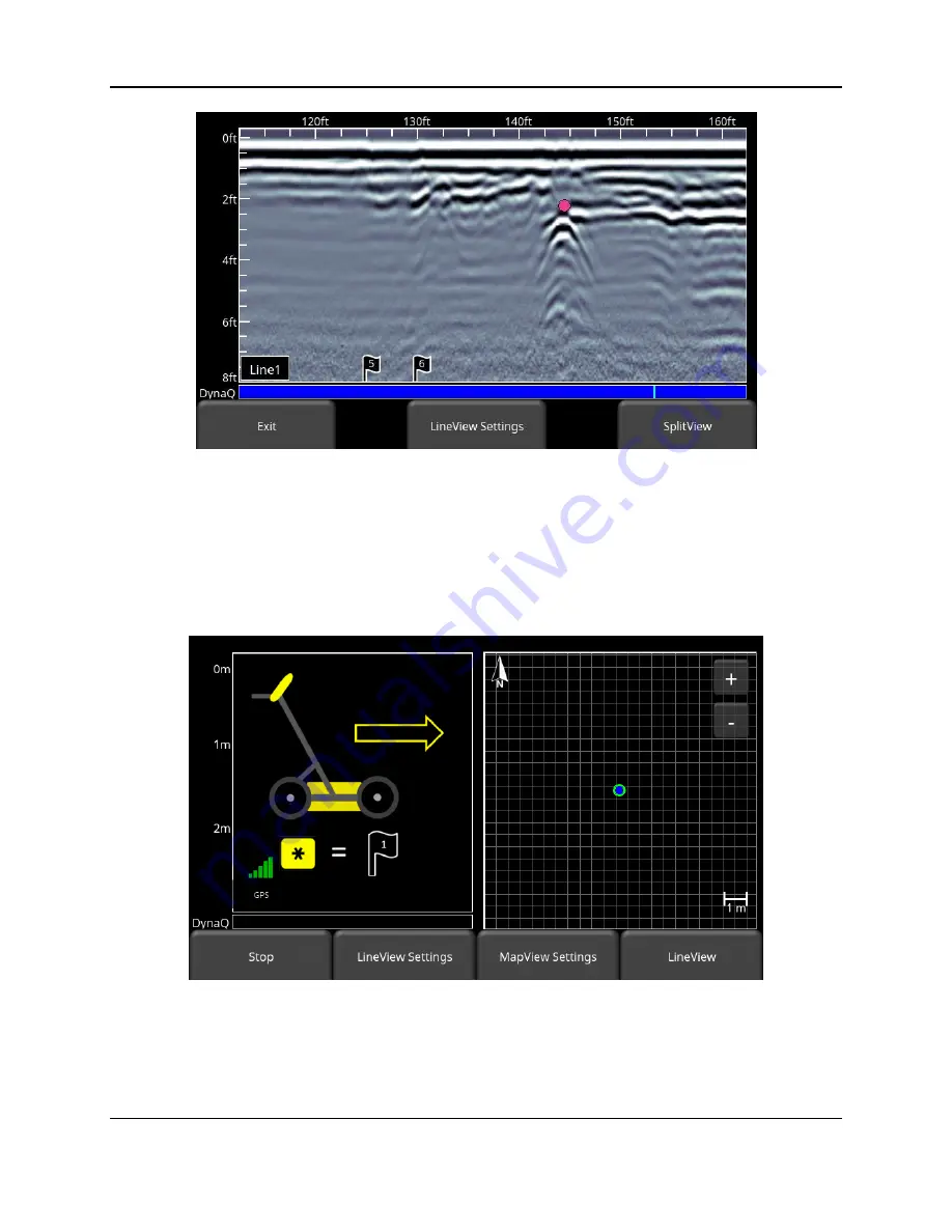
Figure 6-7: Inserting Flags
6.6 SplitView
When the external GPS is connected, the user is able to split the screen to show Line Scan data
being acquired, as well as a real time MapView display. Press the
SplitView
button to see this
view (Figure 6-8). The quality of the GPS signal received is always shown in the lower left of
the LineView display; this is explained at the beginning of this chapter.
Figure 6-8: SplitView display, showing LineView on the left half and MapView on the right half
The current position of the system is shown as a blue dot with a green circle around it on the
MapView display. As the system is moved and data is collected, your position is updated on the
MapView side of the display, The path travelled is initially shown as an orange line. As more
data is collected, part of the line will turn white, while a small section remains orange. This
Summary of Contents for LMX200 Series
Page 1: ...2015 00158 09 ...
Page 2: ...ii ...
Page 4: ...Product Registration iv ...
Page 10: ...x ...
Page 14: ...xiv ...
Page 48: ...Tools Setup 48 ...
Page 52: ...GPR Concepts 52 ...
Page 86: ...SliceView 86 ...
Page 96: ...Capturing Screens E mailing Mini Reports 96 Figure 10 3 Example of a Mini Report ...
Page 104: ...Transferring Data to a PC 104 ...
Page 108: ...Troubleshooting 108 ...
Page 111: ...Care Maintenance 111 ...
Page 112: ...Care Maintenance 112 ...
Page 114: ...Parts List Accessories 114 ...
Page 116: ...Parts List Accessories 116 ...
Page 118: ...Technical Specifications 118 ...
Page 120: ...Appendix A Health Safety Certification 120 ...
Page 128: ...Appendix B GPR Emissions Interference and Regulations 128 ...
Page 130: ...Appendix C Instrument Interference 130 ...
Page 132: ...Appendix D Safety around Explosive Devices 132 ...


