Sequencer COMPACT
Technical brochure
FI 72.0467.0118E
Page 11 / 42
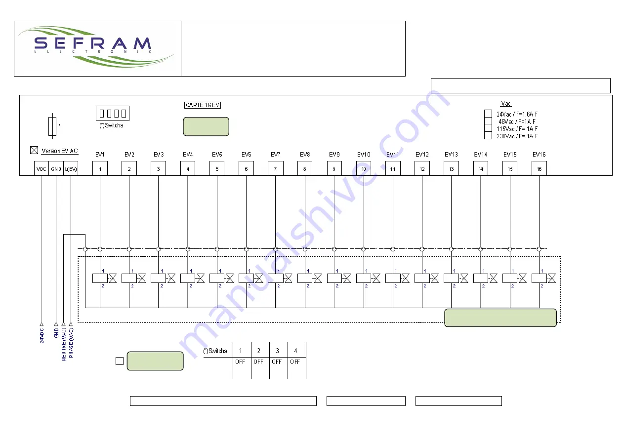
SEQUENCER CARD AC CONNECTION : Example
Card n°0
Card n°0: SV1 to SV16
16x Solenoids valves Vac outputs
Page 1: ...hnical brochure FI 72 0467 0118E Page 1 42 PLACE GUTENBERG 59175 TEMPLEMARS France Tel 33 0 3 20 60 49 49 Fax 33 0 3 20 95 59 62 Email contact sefram eu Web www sefram eu Electronics dedicated to dedu...
Page 2: ...nning faults dust and pressure measures are clearly displayed A graphic representation of pressure dust rejection and analog input allows an easy control of their level An USB key can be plugged to th...
Page 3: ...48Vac 115Vac 230Vac voltage to supply According to power and voltage of the solenoid valve TOUCH SCREEN Size Technology 4 3 inches TFT LCD Tactile Resistive Resolution Colors 480x272 pixels 65536 colo...
Page 4: ...n mounting on support RAIL DIN Dimension of display 129 x 103 x 39mm L x l x P Window 118 8 x 92 8mm L x l CONNECTIONS PRESSURE Pressure pipe to be connected to the sensor Polyurethane tube 4x2 5mm Tu...
Page 5: ...f supplies in case of a failed SV short circuit There is 1 common fuse for the 16 outputs This fuse is on the corresponding output card Version DC Version AC The fuse rating depends on order tension o...
Page 6: ...Link to sequencer card Output Relay running order response Output Relay Alarm analog input High Alarm Low Alarm or fault Output Relay General fault Output Relay High alarm dP Inputs TOR Run order Comp...
Page 7: ...ust control sensor CDM Link to Sequencer card Link to sensor with 4 20 output as a temperature sensor dP measure output GENERAL DEFAULT OUTPUT If default is present contact between C and NC HIGH dP AL...
Page 8: ...ACT Technical brochure FI 72 0467 0118E Page 8 42 Connections Sequencer DC card Link to mother card RS485A output with SQ A input RS485B output with SQ B input Power supply 24Vdc Order outputs SV 24Vd...
Page 9: ...Sequencer COMPACT Technical brochure FI 72 0467 0118E Page 9 42 SEQUENCER CARD DC CONNECTION Example 16x Solenoids valves outputs 24Vdc 25W Card n 0 Link to MOTHER Card Card n 0 SV1 to SV16...
Page 10: ...e FI 72 0467 0118E Page 10 42 Connections Sequencer DC card Supply Voltage 24Vdc Supply voltage SV AC PHASE Order output SV from 1 to 16 Supply VAC NEUTRAL Link to mother card RS485A output with SQ A...
Page 11: ...Sequencer COMPACT Technical brochure FI 72 0467 0118E Page 11 42 SEQUENCER CARD AC CONNECTION Example Card n 0 Card n 0 SV1 to SV16 16x Solenoids valves Vac outputs...
Page 12: ...link towards informations page of CDM Measure of dust rate This display is ON only if a dust sensor has been validated into parameters Configuration of the dust sensor is available on Parameters Menu...
Page 13: ...s automatically reset but for some others it is necessary to reset them manually page current defaults Note If the present display page is different than the main page and if a new default appears we...
Page 14: ...COMPACT Technical brochure FI 72 0467 0118E Page 14 42 Page Current Defaults 1 list of the present defaults with time 2 link towards general main page 3 link towards main page synoptic 4 default rese...
Page 15: ...able at level 0 1 and 2 To reset manufacturer counter press Reset area enable at level 2 6 Press the button to display the manufacturer counter or user counter If manufacturer is displayed the counter...
Page 16: ...e max is set at value 0 This value will be updated when the first max value is observed There is no max value during 3 seconds after the start of declogging cycle 3 Mini load loss measured dP daPa To...
Page 17: ...e is adjustable between 1 to 60 sec see on pressure switch page parameters Example if the sample rate setting is 1 record 60sec then the total recording time is equal to 138 days To insert the USB key...
Page 18: ...have a good knowing of this sensor CDM Sensor to monitor dust emission FI 72 0401 0115E 1 Instantaneous of dust emission rate Value in regarding the alarm threshold Alarm threshold n2 x PR value 2 Mea...
Page 19: ...on on the USB key The sample rate is adjustable between 1 to 60 sec see on Dust Sensor CDM page parameters Example if the sample rate setting is 1 record 60sec then the total recording time is equal t...
Page 20: ...s measures on the USB key The sample rate is adjustable between 1 to 60 sec see on Pressure Switch page parameters Example if the sample rate setting is 1 record 60sec then the total recording time is...
Page 21: ...e 2 link towards Password Setting 3 link towards menu parameters HMI 4 link towards menu languages 5 link towards menu manual mode Setting enabled in level 1 2 6 link towards menu information 7 link t...
Page 22: ...esponds to the manufacturer level allowing to add or cancel functions to the system as well as to adjust parameters of these functions Allow to record some measure dP dust emission analog input and de...
Page 23: ...MI settings 1 Setting of the clock 2 Calibration of the size of the screen Necessary when the touch screen does not react precisely 3 Adjustment of the lightning of the screen 4 Link towards main page...
Page 24: ...42 Page Language settings 1 english 2 Indonesian 3 french 4 language in use 5 link towards page general menu 6 link towards main page synoptic To modify the language in use of the system press the co...
Page 25: ...g cycles following the settings in the controller part number of SVs and duration of times of the cycle The declogging cycles in manual mode are enabled whatever will be the status of running order in...
Page 26: ...System 1 identification of the manufacturer supplier 2 name of the device 3 serial number of the box 4 name of software version identification of software electronic card identification of software H...
Page 27: ...the HMI Once USB key is inserted wait the audio signal which indicates that the system has identified the USB key Press USB recording key validate and wait for the message successful recording recordi...
Page 28: ...u Dust sensor CDM parameters 4 link towards menu Pressure switch parameters 5 link towards menu analog input 4 20mA parameters name of the analog input 4 20mA which is documented in the page analog in...
Page 29: ...nning order not present if value of the load loss dP is smaller than the fan stop threshold 2 This setting is displayed if the detection of the fan stop is set by a low dP value The Fan Stop is detect...
Page 30: ...the cycle will stop where it is at the end of T2 time It will start again from this position 3 Enslavement of declogging with load loss dP 2 possible choices setting enabled in level 2 with dP declogg...
Page 31: ...LE Resting time between 2 declogging cycles Adjustable from 0 to 255 minutes setting enabled in level 1 2 0 inactive 5 T4 AUTO CYCLE If the sequencer did not have declogging cycle during the defined t...
Page 32: ...in level 1 2 3 Adjustment of value n2 from 2 to 33 x PR setting enabled in level 1 2 4 Adjustment of time X from 1 to 33 minutes setting enabled in level 1 2 5 Self learning of the mean dust emission...
Page 33: ...al running 4 High Alarm dP threshold Adjustments from 0 to 500 daPa setting enabled in level 1 2 If dP measure exceeds this threshold more than 5 seconds High Alarm dP If dP measure falls below this t...
Page 34: ...ation of the analog input 5 value of the measured physical value corresponding to the value of the input 4 20mA 4mA see notice of the instrument which is connected to the analog input setting enabled...
Page 35: ...rocess Modbus link is used 2 speed setting 4800 9600 19200 38400 51200 115200 Bauds setting enabled in level 1 3 Number of stop bit setting 1 2 setting enabled in level 1 4 Parity setting Without Even...
Page 36: ...than the alarm threshold which is adjusted in page parameters CDM0 see CDM brochure none on the running check the integrity of filters CDM Alarm Configuration YES Alert and or Alarm threshold is out o...
Page 37: ...onic board If there is at least one fault except the information maintenance number of cycles overpassed the information general fault is given the relay is powered if there is no fault Reset of fault...
Page 38: ...ode If fan stop is detected by load loss measure dP If running order input is off I1 0 the sequencer stops immediately or finishes the ongoing cycle according to the chosen mode If fan stop is noted t...
Page 39: ...y off if fault present Relay REL2 high dP alarm Relay supplied if no high dP alarm Relay off if high dP alarm Relay REL3 analog input alarm Relay supplied if no analog input fault and no high dP alarm...
Page 40: ...e cable for specific exploitation conditions consult us interventions must always be done by a qualified person CALIBRATION When the device leaves our workshop it is adjusted at 0 value for the zero p...
Page 41: ...T TN or IT Nevertheless we recommend that the device is supplied through the intermediary of an insulation transformer for which the primary is supplied between phases and not between phase and neutra...
Page 42: ...except connections and adjustments In case of failure intervention is not allowed and the device must be sent back at the following address CONFORMITY The sequencer COMPACT is in accordance with the E...