4.1.1
Ventilation
4.1.2
Insulation
4.1.3
Electrical Connections
4.2
Lubrication and Bearings
4.2.1
Grease Type
4.2.2
Bearing Operating Temperature
4.2.3
Lubrication Interval
4.2.4
Lubrication Procedure
4.2.5
Lubrication Example
4.3
Trouble Shooting
4.3.1
General Trouble-Shooting Warnings
4.3.2
Trouble-Shooting
Cause
/
Corrective
Action
_________________________________________________________________________________________________________________________
1.0
INSTALLER/OWNER/OPERATOR
RESPONSIBILITY
:
1.1
ELECTRICAL SAFETY
WARNING:
ELECTRICAL SHOCK HAZARD
Electrical connections shall be made by a qualified electrical personnel in
accordance with all applicable codes, ordinances and sound practices.
Failure to follow these instructions could result in serious personal injury,
death and/or property damage. Only qualified personnel who are familiar
with the applicable National Code (USA = NEC) and local codes should
install or repair electrical motors and their accessories.
WARNING:
ELECTRICAL LIVE CIRCUIT HAZARD
Do not touch electrically live parts. Disconnect, lockout and tag input
power supply before installing or servicing motor (includes accessory
devices). Use a voltmeter to verify that power is off before contacting
conductors.
WARNING:
ELECTRICAL GROUNDING HAZARD
Failure to properly ground motors, per the National Electrical Code (NEC)
Article 430 and local codes may cause serious injury or death to
personnel. For general information on grounding refer to NEC Article
250. (Also see “Ground Connections section 3.4.4“).
WARNING:
AUTOMATIC RESET PROTECTOR HAZARD
Do not use automatic reset protectors if automatically restarting the motor
will place personnel or equipment at risk. . Failure to follow this instruction
could result in serious personal injury, death and/or property damage
WARNING:
MANUAL RESET PROTECTOR HAZARD
If a tripped manual reset thermal protector is exposed to a temperature
less than –7°C (20°F) it may reset and restart the motor automatically. If
an application requires a motor with a manual reset thermal protector that
will be operated at temperatures less than –7°C (20°F) contact the
manufacturer to review the application / motor requirements. Failure to
follow this instruction could result in serious personal injury, death and/or
property damage
1.2
MECHANICAL SAFETY
WARNING:
LOOSE PARTS HAZARD
Before starting the motor, remove all unused shaft keys and loose
rotating parts to prevent them from flying off. Failure to follow these
instructions could result in serious personal injury, death and/or property
damage.
WARNING:
ROTATING PARTS HAZARD
Keep extremities, hair, jewelry and clothing away from moving parts.
Failure to follow these instructions could result in serious personal injury,
death and/or property damage.
1.3
ENVIRONMENTAL SAFETY
WARNING:
HAZARDOUS LOCATIONS
(1) The NEC and the local authority having jurisdiction must be consulted
concerning the installation and suitability of motors for use in
Hazardous Locations. The local authority having jurisdiction must
make the final determination of what type of motor is required. The
application and operation is beyond the control of the motor
manufacturer.
(2) Division 1 Hazardous Locations motors can only be modified or
reworked by the manufacturer or a facility that is Listed under UL’s
category “Motors and Generators, Rebuilt for use in Hazardous
Locations”. Failure to follow these instructions could result in serious
personal injury, death and/or property damage.
(3) Do not use a Hazardous Locations motor with a Variable Frequency
Drive (VFD) unless the motor nameplate specifically states that the
motor is suitable for use on Pulse Width Modulated (PWM) type VFD
power. In addition, the nameplate must be marked with the inverter
rating; for example, “2:1 CT”, “2 to 1 Constant Torque”, etc.
2.0 RECEIVING AND INSPECTION
2.1
INITIAL INSPECTIONS
2.1.1
CHECK PACKING LIST AND INSPECT
the
packaging to make certain no damage has occurred in shipment. If
there is visible damage to the packaging, unpack and inspect the
motor immediately. Claims for any damage done in shipment must
be made by the purchaser against the transportation company.
2.1.2
TURN MOTOR SHAFT
by hand to be certain that it
rotates freely.
Note: Shaft seals and bearing seals may add drag.
2.1.3
CHECK NAMEPLATE
for conformance with purchase
order requirements and compliance with power supply and control
equipment requirements.
2.2
HANDLING
:
WARNING:
FALLING OBJECT HAZARD
Eyebolts or lifting lugs, where provided, are intended for lifting
only the motor and accessories mounted by the motor
manufacturer (
unless specifically stated otherwise on the motor).
Utilizing the motor lifting provision to lift other components such as
pumps and gear boxes could result in serious personal injury, death
and/or property damage.
WARNING:
FALLING OBJECT HAZARD
Before using the lifting provision, check the eyebolts and/or other lifting
means to assure they are not bent or damaged and are completely
threaded, seated & secured to the motor. Equipment to lift motor must
have adequate lifting capacity. While lifting the motor DO NOT stand
under or in the vicinity of the motor. Failure to follow these instructions
could result in serious personal injury, death and/or property damage.
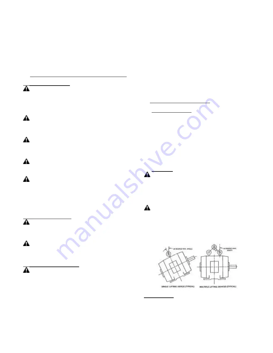
2.2.1
LIFTING ANGLE LIMITATIONS
2.3 STORAGE:
Motors, not put into service immediately, must be
stored indoors in a clean, dry location. Avoid locations with large
temperature swings that will result in condensation. Motors must be
covered to eliminate airborne dust and dirt.
If the storage location
exhibits high vibration, place isolation pads under motor to minimize
damage to motor bearings.
Summary of Contents for BW 10
Page 26: ......
Page 27: ......
Page 28: ......
Page 30: ......
Page 32: ......
Page 63: ......
Page 65: ...Section 1 General Information ii Table of Contents MN400 ...
Page 79: ...3 6 Maintenance Troubleshooting MN400 ...
Page 80: ...Baldor District Offices Baldor District Offices Baldor District Offices ...
Page 82: ......
Page 84: ......
Page 85: ...Meadowbank mining Corp ACP 700R Technical Data Sheet Reference NC01 DOSING PUMP ...
Page 86: ......
Page 111: ......
Page 112: ......
Page 113: ......
Page 121: ......
Page 122: ......
Page 123: ......
Page 124: ......
Page 158: ...BIM 1010 2005 03 6 www nord com ...
Page 162: ...BIM 1010 2005 03 10 www nord com PARTS LIST ...
Page 163: ...BIM 1010 2005 03 11 www nord com NOTES ...
Page 180: ......
Page 181: ......
Page 186: ......


