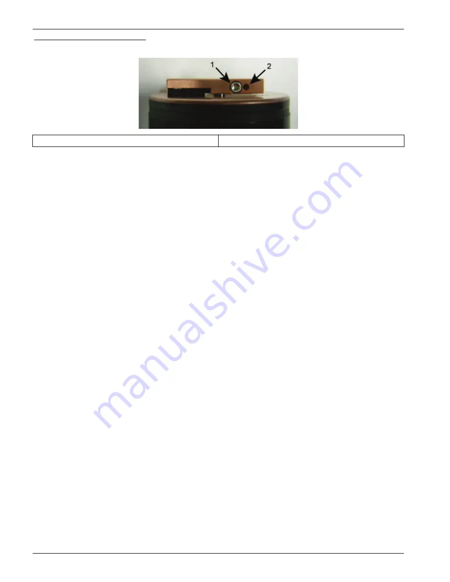
Figure 9 Bio-wiper screw holes
1
the screw in the clamping hole
2
the expander hole
3.
Lift the Bio-wiper off of the faceplate.
4.
If used, remove the jacking screw.
5.
Use a small Phillips screwdriver to remove the screws that attach the faceplate to the
optics face.
6.
Keep the screws.
7.
Clean the Bio-wiper and faceplate with soapy water.
8.
Rinse and dry thoroughly.
9.
Use a Scotch-Brite
®
or similar pad to buff the Bio-wiper and faceplate until they are
shiny.
10.
Use an isopropyl alcohol-saturated cotton swab to clean the Bio-wiper shaft and the
shaft hole.
11.
Make sure the Bio-wiper and faceplate dry completely.
12.
Attach the faceplate again.
13.
Make sure the screw used to attach the Bio-wiper is in good condition.
The 3/32" hex key must fit into the screw's socket.
14.
If the screw is damaged, use a new screw from the spare parts kit that the
manufacturer supplies with the sensor.
These screws are 4-40 x 3/8" 316 stainless steel and are treated with anti-seize.
15.
Insert a jacking screw into the expander hole of the Bio-wiper. Turn it slowly until the
Bio-wiper goes onto the shaft easily.
16.
Put the clean Bio-wiper over the shaft but do not twist the Bio-wiper.
17.
Make sure to remove the jacking screw before tightening the 3/32-inch clamping
screw.
18.
Use the commands in the software to put the Bio-wiper into the closed position.
The Bio-wiper covers the optics.
19.
Set the clearance between the Bio-wiper and the faceplate to approximately 0.6 mm.
Note: If the Bio-wiper is has too much bend because it is too close to the faceplate, the motor
will use too much current. If it is not close enough to the faceplate, the Bio-wiper will not keep
the optics clean.
Sensor maintenance
26


