1
03/2017
© Danfoss
VUIGB602
www.heating.danfoss.com
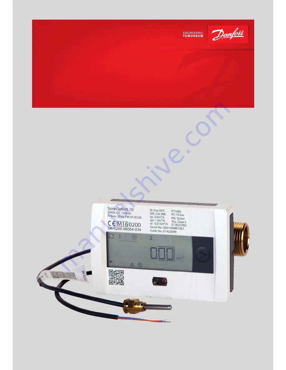
Installation & User Guide
SonoSelect and SonoSafe
energy meters
Page 1: ...1 03 2017 Danfoss VUIGB602 www heating danfoss com Installation User Guide SonoSelect and SonoSafe energy meters...
Page 2: ...2 Danfoss Energy Meters 2017 03 VUIGB702 Installation User Guide SonoSelect and SonoSafe Note To ensure latest version of declaration please visit danfoss com...
Page 3: ...ow sensor installation 5 2 4 Mounting orientation calculator 5 2 5 Mounting of O ring and temperature sensor 6 2 6 Communication Expansion modules 7 2 7 Installation of module cable 10 2 8 Battery 11...
Page 4: ...ed the meter will set alarm E13 in display Don t open unless for adding communica tion module replacing battery or installing cables Reset requires Bluetooth dongle 014U1963 and SonoApp service tool S...
Page 5: ...stallation Heat meters have red temp sensor in supply pipe and all cooling meters have blue temp sensor in supply pipe 2 3 Flow sensor installation Pipe position No limitations but avoid positions whe...
Page 6: ...w sensor installation 1 Mount O ring on pin 2 Insert pin with O ring 3 Position O ring 4 Remove pin 5 Moist and insert sensor probe Tighten at torque 12 2 Nm To ensure accuracy and a tight seal the se...
Page 7: ...he display Wired M Bus is galvanically isolated from C and pulse inputs The two pulse inputs can be programmed independently of each other see specification for pulse input module M Bus primary Lithiu...
Page 8: ...evel input threshold 0 5 V Pull up resistor 100 k Pulse length 100 ms Maximum frequency 5 Hz Pulse inputs According to EN1434 2 section 7 1 5 Classification of pulse input devices Class IB Battery lif...
Page 9: ...orange 24 Meter bus blue or orange 25 Pulse input Pulse input 1 Brown 50 Pulse input 1 White 51 Pulse input 2 Brown 52 Pulse input 2 White 53 Cable specification Pulse input cables 10 m To ensure IP...
Page 10: ...to enclosure 4 Insert module follow ing guide on PCBA cover Insert cable through hole connect cable and fix to screw termi nals matching color and terminal numbers Fix cable s to cable relief Outer ja...
Page 11: ...n en closure 3 Disconnect battery connector and remove battery 4 Short circuit battery connectors on PCB using a small flat head screwdriver 5 Connect new battery to PCB 6 Fit battery in enclosure 7 C...
Page 12: ...s 4 For SonoSelect Run installation check using Bluetooth dongle 014U1963 and SonoApp service tool 3 2 Supply return configuration Only available for SonoSelect Use Bluetooth dongle 014U1963 and SonoA...
Page 13: ...e SonoSelect and SonoSafe 4 Function overview 4 1 Menu structure Hours Alarm Energy Volume LOOP 1 Supply temp Display test All on Power Flow LOOP 2 Accounting date Monthly date 1 Monthly date 12 LOOP...
Page 14: ...turn temperature Decimal emphasizer Temperature difference Units field 4 3 Alarms E01 System error E10 Transducer error E02 PCB error E11 Outside measured range E03 Battery empty less than 1 month E12...
Page 15: ...Module PCB 12 Bottom part PC 13 Temperature sensor 6 Disposal Item Material Disposal Battery AA cell Lithium thionyl chloride 620 mg Lithium Approved deposit for lithium batteries PCBA with display a...
Page 16: ...in catalogues brochures and other printed material Danfoss reserves the right to alter its products without notice This also applies to products already on order provided that such alterations can be...