


Scientific
SMO1000E
118/185
LIN Triggering and Serial Decode
Please take the order of “
Setup for LIN Signals
”, “
LIN Triggering
” and “
LIN
Decode
” to
trigger and decode the signals.
Setup for LIN Signals
There are two steps of setting the LIN signal, connecting the signal to oscilloscope,
specifying the parameters of each input signal.
1. Press the
Decode
key to enter the DECODE function menu.
2. Press the
Decode
softkey and select the desired slot (Serial 1 or Serial 2).
3. Press
Protocol
softkey and then select
LIN
by turning Universal Knob.
4. Press
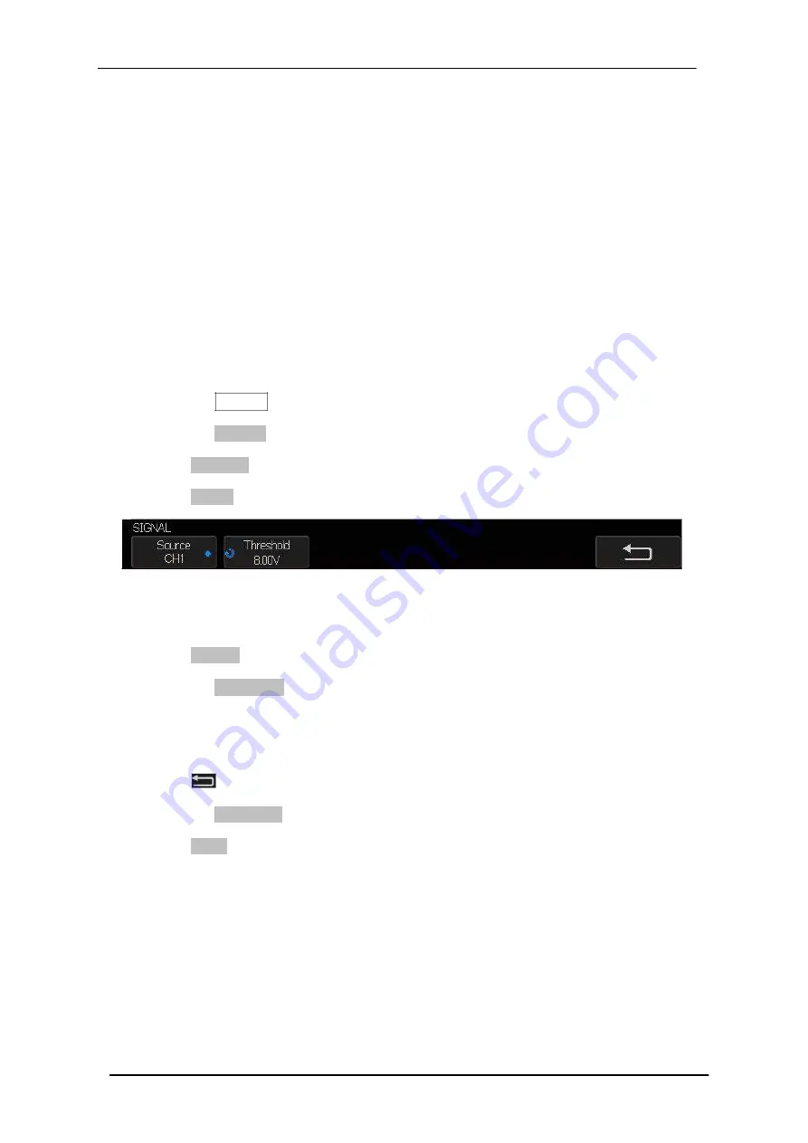
Signal
softkey to enter the
SIGNAL
menu as Figure 58 shows.
Figure 58 LIN SIGNAL Menu
5. Press
Source
softkey to select the channel that is connected to the LIN signal.
6. Press the
Threshold
softkey and set the LIN signal’s threshold voltage level by
Universal Knob. The threshold voltage level is for decoding, and it will be regard as
the trigger voltage level when set the trigger type to serial.
7. Press
softkey to return previous menu.
8. Press the
Configure
softkey to enter the
BUS CONFIG
menu.
9. Press
Baud
softkey to set baud rate.
The baud rate can be set as predefined value.
If the desired baud rate is not listed, select
custom
option, press the
Custom
and
turn the Universal Knob to set the desired baud rate.
Summary of Contents for SMO1000E
Page 1: ...Digital oscilloscope SMO1000E User Manual ...
Page 17: ...Scientific SMO1000E 17 185 Appearance and Dimensions Figure 1 Front View Figure 2 Top View ...
Page 54: ...Scientific SMO1000E 54 185 Figure 12 x Interpolation Figure 13 Sinx x Interpolation ...
Page 82: ...Scientific SMO1000E 82 185 Figure 28 Relative Window Trigger ...
Page 84: ...Scientific SMO1000E 84 185 Figure 29 Interval Trigger ...
Page 109: ...Scientific SMO1000E 109 185 Figure 53 UART Trigger ...


