3 Assembly and start-up
12
SCHMIDT
®
ServoPress 605-660
– V1.1
You will find ram dimensions, the maximum dimensions and the maximum
weights for the upper tools in chapter "6.1 Technical data".
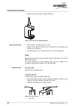
For mounting the upper tool, a centric dowel pin hole with a set screw is
available for fixing it.
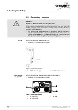
Insert the clamping pin into the dowel pin hole of the ram.
Fasten the upper tool using the set screw.
Figure 4: Fastening options at the ram (example)
1
Set screw
2
Dowel pin hole
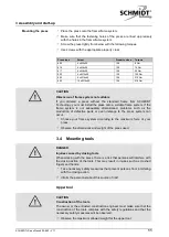
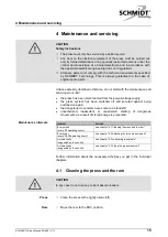
The ram has a distortion lock for the upper tool.
Figure 5: Distortion lock on the ram (example)
1
Slot (ServoPress 605)
2
Dowel hole (ServoPress 616-660)
3
Threaded hole (ServoPress 616-
660)
Lower tool
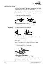
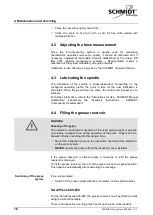
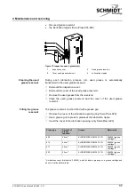
For mounting the lower tool, a table bore and a T-slot are available.
Place the lower tool on the table plate.
Screw the lower tool down to the table plate.
Figure 6: Frame with table plate (example)
1
Table bore
2
T-Slot
For frames with a screwed fixture mounting plate, the fixture mounting plate
is aligned with the ram but not pinned.
Distortion lock


