CANopen Field Bus
84
Operating Manual XCx 300 / 500 / 540 Version 09/08
7.4
Parameterizing and Diagnosis Functions
The PLC can initiate parameterizing and diagnosis functions in the
CAN processor* by transmitting a code.
Function
0
No function
1,17
Read and set nodenumber (node ID), range: 1..127
Reboot required
2
Read and set baud rate, range: 1..8
Reboot required
3 ... 5
Reserved
6
Output CAN status code
7
Output error status
8
Output firmware version
9..15
Reserved
16
Output effective runtime of CAN stack (in 1/100 ms)
17..19
Reserved
20
Output and set startup delay, range: 1..60 s
21...101
Reserved
102
Output and set cycle time of CAN stack, range: 1..10 ms
Reboot required
103...254
Reserved
255
Reset
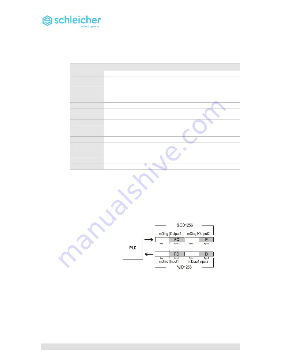
The PLC requests a function by entering the required function code in
the mDiag1Output1 variable.
If a function is to be sent with parameter, first the parameter has to be
entered in mDiag1Output2 and then the function code in
mDiag1Output1.
After the function has been executed the function code is always
displayed in mDiag1Input1, while the diagnosis data can be read in
mDiag1Input2
.
FC
=
F
unction
C
ode
P
=
P
arameter
D
=
D
ata
Direct assignment in 32-bit variables is also possible (e.g. %QD1256
and %ID1256).
* Here "CAN processor" refers to the hardware and software of the
CANopen interface.


