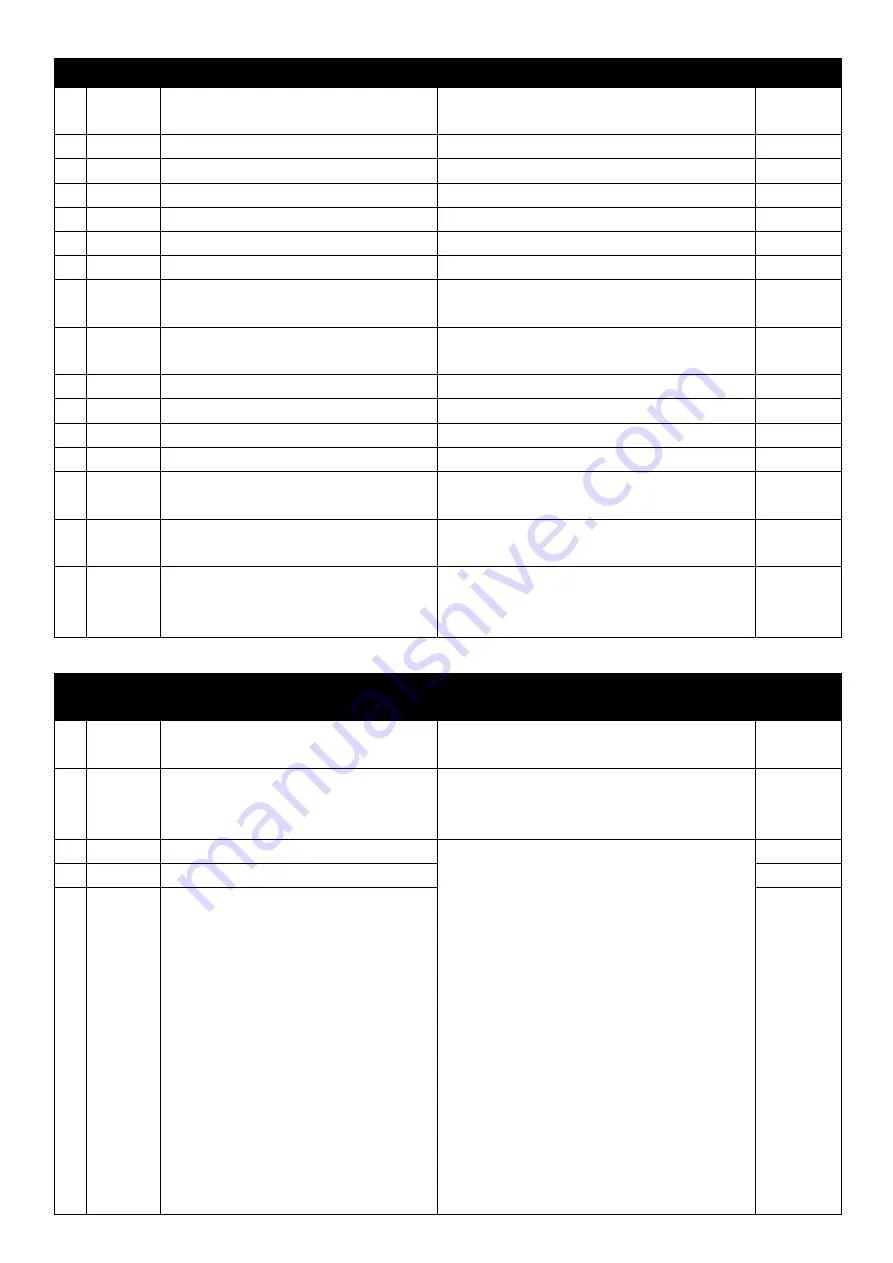
Savch S200 Series User Manual Download Page 26


22 

01:Basic Parameters


Set during running available    * the values of different machine models are different.


Parame

ter 

Parameter functions 

Setting range 

Factory 

setting 


01-03 

Max voltage frequency setting 

10.00

600.00 Hz 

50.00 


01-04 

Max output voltage setting 

200.0

500.0*V 

380.0* 


01-05 

Intermediate frequency setting 

1.00

600.00Hz 

1.50 


01-06 

Intermediate voltage setting 

2.0

500.0*V 

12.0* 


01-07 

Min output frequency setting 

0.00

20.00Hz 

1.50 


01-08 

Min output voltage setting 

2.0

100.0*V 

12.0* 


01-09 

Upper limitation of output frequency 

setting 

1.00

  600.00 Hz 

600.00 


01-10 

Lower limitation of output frequency 

setting 

0.00

600.00 Hz 

0.00 


01-11 

1

st

 acceleration time setting 

0.10

400.00 Sec 

10.00 


01-12 

1

st

 deceleration time setting 

0.10

400.00 Sec 

10.00 


01-13 

2

nd

 acceleration time setting 

0.10

400.00 Sec 

10.00 


01-14 

2

nd

 deceleration time setting 

0.10

400.00 Sec 

10.00 


01-15 

Motor Stop mode selection 

0:Deceleration and stop 

1:Coast to a stop 


01-16 

Inhibit REV rotation function setting 

0:REV rotation available 

1:REV rotation inhibited 


01-17 

Carrier frequency selection 

0:fc=3kHz            1:fc=6 kHz   

2:fc=8 kHz            3:fc=10 kHz   

4:fc=12 kHz          5:fc=15 kHz 


02:External Terminal Parameters 


Set during running available    * the values of different machine models are different.


Parame

ter 

Parameter functions 

Setting range 

Factory 

setting 


02-00 

2 wire style/3 wire operation control 

0:Fwd run/stop, Rev run/stop 

1:Run/stop, Rev run/fwd run 

2:Three wire operation control 

0   


02-01 

Multi-functional input option 1 

0:Multi-step speed command 1 

1:Multi-step speed command e 2 

2:Multi-step speed command 3(EF) 

3:Jog frequency command 

4:Acceleration/Deceleration inhibition 

command 

5:Switching of 1

ST

 and 2

nd


acceleration/deceleration time 

6:reserved 

7:reserved 

8:Up command 

9:Down command 

10:RST input 

11:EF input 

12:Set frequency in the keypad while select 

the specified ACI frequency. 

3   


02-02 

Multi-functional input option 2 


02-03 

Multi-functional input option 3 

Summary of Contents for S200 Series

Page 1: ...S200 Series Inverter VF General Type User Manual User Manual ...

Page 2: ...16 04 01 SAVCH electric provide a full range of technical support for our customers All users could contact with the nearest SAVCH office or service center also could contact with our headquarters directly SAVCH Electric reserves the copyrights and all rights Subject to change without further notice ...

Page 3: ...S200 4T7 5G 4T15P Diagram for removing and mounting the front cover Remove the front cover according to the following steps Assemble the front cover according to the following steps ...

Page 4: ...th Motor 19 4 LIST OF DESCRIPTIONS FOR FUNCTIONAL PARAMETERS 21 5 DESCRIPTION OF FUNCTIONAL PARAMETERS 28 0 System parameters 28 1 Basic Parameters 29 2 External Terminal Parameters 34 3 Analog output input function parameters 39 4 Multi step Speed and Program Operation Parameters 41 5 Special Parameters 41 6 Motor setting parameters 45 7 Protection Parameters 45 8 Communication Parameters 49 11 S...

Page 5: ...serious damage to inverter or machine may be resulted DANGER Never connect wires while power on Do not check components or signal for circuit board during operation Do not dismantle or change inner wire circuit or components unnecessarily Make sure grounding terminals are correctly grounded 220V level rounding Ⅲ 440V level Special Grounding CAUTION Do not perform a withstand voltage test for compo...

Page 6: ... panel a fan shall be prepared to make sure temperature lower than 40 thus over heating or a fire hazard shall be avoided Operator shall be dismantled or refitted after power supply is off Fixed operator shall be processed as diagram shows to prevent operator fault or no display CAUTION Make sure applied power supply comply with label showed on the right of the machine Failure to observe this may ...

Page 7: ...ill on During check and maintenance CAUTION Ambient temperature for operating the inverter shall be 10 to 40 and 90 RH non moistring condensation CAUTION After removing the dust cover ambient temperature for operating the inverter shall be 10 to 50 and 95 RH non moistring condensation However under this condition the ambient environment must be without drips of water or metal dust If there are the...

Page 8: ...ammable materials Extreme low temperatures Extreme high ambient temperatures Above 40 Large impelling Salt or saline Rain moisture Iron chips and dust Electromagnetic waves and ultra high angle rays For example locations of welding machines and etc Oil cool Below 10 degrees Celsius Force Force Force Force Force Force Salt ...

Page 9: ...ic interference Avoid using together with welding machine or dynamic machines Vibration If inverter must be used in this environment an anti vibration pad is necessary Attention shall be attached to clearance of inverters allocated closely A fan shall be installed to make sure temperature is lower than 40 INSIDE THE CABINET FALSE AIR EXCHANGE FAN INSIDE THE CABINET INSIDE THE CABINET CORRECT FALSE...

Page 10: ...80 460V 50 60Hz OUTPUT 3PH 0 460V 6 3kVA 8 2A FREQUENCY RANGE 0 1 600Hz S N NJ3019380000037 SAVCH ELECTRIC CO LTD Designed by Savch Electric S200 4T 3 7 G 0 75 0 75kW 1 5 1 5kW 2 2 2 2kW 3 7 3 7kW 5 5 5 5kW 7 5 7 5kW 11 11kW 15 15kW G Constant torque load For general use P Variable torque load 4T 440V Three phase Product series ...

Page 11: ...om 0 01 to 50 0Hz from STOP braking 0 to 100 of the rated current Starting time 0 0 to 5 0 sec Stopping time 0 0 to 25 0 sec Braking torque 20 125 shall be available if connected with purchased braking resistor externally for 1 to 25HP equipped within the electric crystals for 30HP braking unit module shall be connected externally Model S200 4T G 0 75 1 5 2 2 3 7 4 0 5 5 7 5 11 15 Output Max appli...

Page 12: ...nction Setting max min output frequency momentary power off restarting fault restarting setting of S curve acceleration deceleration time auto voltage stabilizing output modulation digital frequency output signal fault records parameters locking reset to factory setting inhibiting reverse run over current stalling prevention over voltage stalling prevention electrical thermal relay Protection Func...

Page 13: ...more than one motor were driven simultaneously by one inverter the current of these motors when running shall below capacity of the inverter And each motor shall be prepared with a thermal relay in appropriate capacity Phase advance capacitors and other capacity elements such as LC or RC shall not be fixed between the inverter and motor List of applicable no fuse breaker for S200 series 440V Serie...

Page 14: ... use the magnetic contactor as RUN STOP switch for inverter Power Improving AC Electric Reactor If power supply of large capacity Above 600k VA is used an AC reactor can be added to inverters which is below 220 440V 15Kw thus the power of power supply shall be improved Input side Noise Filter The Input side Noise Filter must be applied if inverter has electronic induction load around S200 Inverter...

Page 15: ...r or isolating transformer shall be added MCCB Machine MCCB Power supply S200 Noise filter IM MCCB IM S200 Machine Isolated transformer Power suppy Good effect may not be received if general use noise filters are applied MCCB Power supply IM S200 Machine Noise filter in general use MCCB MCCB Power supply IM S200 Machine Noise filter in general use MCCB Interference during transmission can be prohi...

Page 16: ...shall connect grounding terminals Distance for wiring shall be 50m or less Armor Shielding Layer Never connect Insulate these parts with insulation tape To ground terminal See filter Wiring Specification C Grounding terminal for inverters shall be grounded properly Below 100Ω Category Ⅲ Below 10Ω Special AWG shall be taken as standard for ground wire Ground wire shall be as short as possible Never...

Page 17: ...FWD TRG Count Triggering signal input DFM Digital frequency meter Digital signal Common terminal DCM 0V RS 485 serial connected communication board SG SG Signal terminal Signal terminal Computer S L2 S T L3 T R L1 R MCCB Induction motor U V W IM Assisted power supply 24V Analog frequency flow meter AFM ACM Analog signal terminal common 10V Analog voltage frequency command AVI1 0 10V Analog current...

Page 18: ...B2 MI1 MI2 MI3 MI4 FWD REV TRG DCM DCM MO1 MCM 24V AVI1 AVI ACI ACM AFM 10V SG SG Relay output terminal RA RB RC wiring RB RC normally closed RA RC normally opened If it drives inductive load such as electromagnetic relay contactor should be installed an absorbing circuit of surge voltage Such as RC absorption circuit notes the leakage current should be less than the control contactor and relay to...

Page 19: ...ly 10V AVI ACM Analog voltage frequency reference 0 10V Max output frequency ACI ACM Analog current frequency reference 4 20mA Max output frequency AFM ACM Analog frequency current meter 0 10V Max output frequency SG SG Serial connected communication board RS485 Serial connected communication connector 24V DCM Assisted control power supply DC 20V 24V 50mA Max Pay attention to insulate the control ...

Page 20: ...16 Inverter Main body figure Small power keypad IP03 External dimensions and Installation dimensions Large power keypad IP05 External dimensions and Installation dimensions ...

Page 21: ...ay Mode Key Decrement Set Key Increment Set Key STOP RRESET Key Using name in manual Function Descriptions PRGM DATA PRGM DATA Key Parameter Set Key For reading the modified parameters setting of the drive MODE MODE Key Display Mode Key Click this key to display the successive changing items for selection JOG JOG Key JOG Key Click this key to perform JOG running Data Left Moving Convenient to modi...

Page 22: ...f internal counter Displaying output current of U V and W at output side of the AC motor drive Displaying parameter project Content of this parameter shall be displayed by depressing PRGM DATA Displaying parameter content value Modified materials shall be stored by depressing PRGM DATA If END information as diagram left shows lasts for about 1 sec it means that data has been received and memorized...

Page 23: ...into the following categories Both frequency and operation reference are controlled by keyboard 1 01 1 Factory setting IM Operation reference is controlled by external terminals STOP key on keyboard available Two line operation control REV STOP and FWD STOP 2 00 0 DCM FWD REV STOP FWD STOP REV IM Frequency reference is controlled by keyboard Operation reference is controlled by external terminals ...

Page 24: ... Configuration 1 2 00 2 this time 2 03 default 2 Other functions can not be used DCM STOP RUN FWD EF REV FWD REV IM Frequency reference is input by analog signals DC 0 to 10V DC 4 to 20mA Operation reference is controlled by keyboard 1 00 2 or 3 IM ACM 10V AVI ACI 4 20mA 0 10V 3 2 1 ...

Page 25: ...ying DC BUS voltage 2 Displaying count value 3 Displaying rotating speed 0 01 Basic Parameters Set during running available the values of different machine models are different Parame ter Parameter functions Setting range Factory setting 01 00 Master Frequency Input Setting 0 The master frequency input is controlled by digital exerciser 1 Reserved panel potentiometer input 2 Master frequency is in...

Page 26: ... 15 Motor Stop mode selection 0 Deceleration and stop 1 Coast to a stop 0 01 16 Inhibit REV rotation function setting 0 REV rotation available 1 REV rotation inhibited 0 01 17 Carrier frequency selection 0 fc 3kHz 1 fc 6 kHz 2 fc 8 kHz 3 fc 10 kHz 4 fc 12 kHz 5 fc 15 kHz 2 02 External Terminal Parameters Set during running available the values of different machine models are different Parame ter P...

Page 27: ...utput terminal 2 MO2 reserved 1 02 11 Random frequency agreement setting 0 00 600 00 Hz 0 02 12 Multifunctional output contactor indication Normally Open Contactor RA RC Normally Closed Contactor RB RC 0 Fault reference 1 Reference during running 2 Set frequency agreement reference 3 Random frequency agreement reference 4 non zero speed 5 Over torque detection reference 6 reserved 7 Low voltage de...

Page 28: ... models are different Parame ter Parameter functions Setting range Factory setting 05 00 DC braking current level setting 0 100 0 05 01 DC braking time setting at starting 0 0 5 0 Sec 0 0 05 02 DC braking time setting at stopping 0 0 25 0 Sec 0 0 05 03 DC braking starting frequency at stopping 0 50 00 Hz 0 05 04 Restarting after momentary blackout 0 unavailable 1 tracking down 2 tracking up 0 05 0...

Page 29: ...ferent machine models are different Parame ter Parameter functions Setting range Factory setting 07 00 Over voltage stall prevention function setting 0 Unavailable 1 Available 1 07 01 Over current stall prevention level setting in acceleration 50 200 160 07 02 Over current stall prevention level setting during running 50 200 160 07 03 Electrical thermal relay selection 0 Act in standard motor 1 Ac...

Page 30: ... 17 OL1 Electrical thermal relay 0 07 10 Recent 2nd fault record 07 11 Recent 3rd fault record 08 Communication Parameters Set during running available the values of different machine models are different Parame ter Parameter functions Setting range Factory setting 08 00 Communication address 0 254 1 08 01 Communication transmitting speed 4 8 115 2 kbits s 9 6 08 02 Transmitting fault treatment 0 ...

Page 31: ...tion AVR 0 Start AVR 1 Cancel AVR 2 Deceleration cancel AVR 0 12 07 Rotation speed displayed coefficient 0 300 100 13 Special Parameters Set during running available the values of different machine models are different Parame ter Parameter functions Setting range Factory setting 13 00 Parameter protection code input 0 9999 0 4 Record code error time 0 13 01 Parameter protection code setting 0 9999...

Page 32: ...ctory setting Type Setting Setting range Display according to machine model This parameter displays the rated output voltage of drive User can view this parameter display value to check the drive is correct or not 00 02 Rated Current Display Factory setting Type Setting Setting range Display according to machine model This parameter displays the rated output current of drive User can view this par...

Page 33: ...igital exerciser 1 Reserved 2 Master frequency is input by analog signals AVI1 DC0 to 10V 3 Master frequency is input by analog signals ACI DC 4 to 20mA DC 0 to 5V 4 Master frequency is controlled by RS485 communication interface 5 Master frequency is controlled by external UP DOWN pin 6 Reserved This parameter is used to set the AC drive main frequency source However the actual AC drive running f...

Page 34: ... motor as indicated on the motor nameplate 01 05 Intermediate frequency setting Factory setting 1 50 Setting range 1 00 600 00 Hz This parameter shall be used to set intermediate frequency for a random V f curve V f ratio of Min frequency to Intermediate frequency shall be determined by this setting 01 06 Intermediate voltage setting Factory setting 12 0 Setting range 2 0 500 0 V This parameter sh...

Page 35: ...03 50 00 01 04 220 0 01 05 25 00 01 06 50 0 01 07 1 30 01 08 10 0 3 High Starting Torque Factory setting N0 Setting value 01 02 60 00 01 03 60 00 01 04 220 0 01 05 3 00 01 06 23 0 01 07 1 50 01 08 18 0 Factory setting N0 Setting value 01 02 50 00 01 03 50 00 01 04 220 0 01 05 2 20 01 06 23 0 01 07 1 30 01 08 14 0 01 09 Upper limitation of output frequency setting Factory setting 600 00 Setting ran...

Page 36: ...c time but in this time It does not work open or never to be set to this function for switching Acc Dec time then the AC drive will decelerate according to the 1st Dec time This parameter is determined by the time which the AC motor drive required when it decelerate from max frequency 01 02 to 0 Hz The rate is linear unless S Curve is Enabled 01 13 2nd acceleration time setting Factory setting 10 ...

Page 37: ...t by 1 12 or 1 14 AC motor drive decelerate to min output frequency 1 07 and then machine stops Coast to a stop AC motor drive stops output immediately and motor runs freely in load inertia and then stops Deceleration and stops Coasting 01 16 Inhibit REV rotation function setting Factory setting 0 Setting range 0 REV rotation available 1 REV rotation inhibited This parameter is set to the AC motor...

Page 38: ...oes not affect the carrier shall be reduced 2 External Terminal Parameters 02 00 2 wire style 3 wire operation control Factory setting 0 Setting range 0 Forward run stop Reverse run stop 1 Run stop Reverse run forward run 2 Three line operation control This parameter sets the external control operation configuration of AC moter drive there are three different control modes 02 00 External terminal ...

Page 39: ...ed commands 1 to 3 groups are used to determine a command frequency via the multi step speed settings 04 00 to 04 06 2 3 When Closed the jogging frequency is selected and performed 3 4 When Closed the output frequency remains constant 4 5 When Open the AC drive accelerates decelerates according to the values set by ACCEL time 1 and DECEL time 1 01 11 12 When Closed the AC drive accelerates deceler...

Page 40: ...999 This parameter sets a specified count value When the internal counter which external terminal TRG is located in the control circuit it starts to count from bottom to the count value the specified output signal terminal MO1 will be closed assuming 02 09 is set to 3 until the count value 02 07 opened upon arrival 02 07 Count value agreement setting Factory setting 1 Setting range 1 9999 This par...

Page 41: ...l have a different system mark output Terminal Parameter External terminal M01 MCM open collector output 2 09 External terminal M02 MCM open collector output 2 10 Action description for contactor 0 Reference during running This contactor shall be CLOSED during AC motor drive output or FWD REV run reference input 1 Set frequency agreement reference This contactor shall be CLOSED when output frequen...

Page 42: ...RA RC NO RB RC NC Factory setting 7 Setting range 0 Fault reference 1 Reference during running 2 Set frequency agreement reference 3 Random frequency agreement reference 4 Non zero speed 5 Over torque detection reference 6 Reserved 7 Low voltage detection reference LU Set 02 12 according to the above table can choose multi function instructions output action signals in different systems 02 13 Anal...

Page 43: ...n any type of voltmeter If the full scale of less than 10 v meter Parameter 02 14 setting way refer to the following formula Parameter 02 14 full scale voltage meter 10 100 Example When using a full scale for 5 v voltage meter adjust the parameters of 02 14 to 50 If the parameter 02 13 is set to 0 the VDC will be corresponding to the max output frequency 3 Analog output input function parameters 0...

Page 44: ... Analog Input Level 03 02 Analogue Input Filter Time Factory setting 0 05 Setting range 0 01 2 00 Sec Control terminal AVI ACI input analog signals often contain noise Noise will affect the stability of the control the input filter filter out the noise Setting time constant is too large stably control but control response is poor conversely quick response but it may not be able to control stably I...

Page 45: ...otor current level Set dc braking current composition ratio 1 Ac motor drive current rating of 100 When this parameter is set begin at a lower current level then increase the value until sufficient holding torque is achieved The rated motor current cannot be exceeded 05 01 DC braking time setting at starting Factory setting 0 0 Setting range 0 0 5 0 Sec This parameter is to set time lasting of DC ...

Page 46: ...f power supply breaking time exceeds Max allowable time 05 05 output of AC motor drive shall stop after power resupplied 05 06 After power is recovered tracking time B B time Factory setting 0 5 Setting range 0 3 5 0 S If power supply interruption is detected AC motor drive shall stop output and shall not be re started until after set time by this parameter It s preferred to provide output side re...

Page 47: ...eceleration time setting Factory setting 3 00 Setting range 0 10 400 00S This parameter determines this time Jogging acceleration deceleration time required for the AC Drive to ramp from 0 Hz to the max output frequency 01 02 and this time Jogging acceleration deceleration time required to ramp from the max output frequency 01 02 to 0 Hz 05 10 Setting of S curve acceleration deceleration time rese...

Page 48: ... 00 05 13 Hopping frequency 3 0 00 Setting range 0 00 600 00 Hz This parameter determines the three hopping frequencies which in conjunction with 05 14 Hopping frequency width will cause the AC drive to skip operation at these frequency ranges 05 14 Hopping frequency width setting Factory setting 0 10 Setting range 0 1 20 0 Hz This parameter determines the frequency band of a given Hopping frequen...

Page 49: ...le setting the value for 06 02 If the value is too high the motor might overheat or be damaged 06 03 Slip compensation increment Factory setting 0 0 Setting range 0 0 10 0 Since load and slip shall increase when AC motor drives induction motor this parameter set value 0 0 10 0 can set compensation frequency to decrease slip and provide the motor running speed under rated current approach synchrono...

Page 50: ...quency the drive will only resume acceleration when the current is less than the setting value 07 02 Over current stall prevention level during running Factory setting 160 Setting range 50 200 During operation of AC motor drive provided that output current exceeds set value of 7 02 Over current stall prevention level during running output frequency shall be decreased by AC motor drive to prevent m...

Page 51: ... categories available Short time rated standard rated and long time rated 07 05 Over torque detection function option Factory setting 0 Setting range 0 No detection 1 Over torque detection oL2 during constant speed running stop running after detection 2 Over torque detection oL2 during constant speed running continue to run after detection 3 Detect over torque when motor running after detected ove...

Page 52: ...ault record Factory setting 0 07 10 Recent 2nd fault record 0 07 11 Recent 3rd fault record 0 Display contents 0 No abnormal 1 SC IGBT short circuit protection 2 OV Over voltage 3 OC Over current 4 OL Inverter over load 5 OH Over heating 6 EF External fault 7 OCA the acceleration current is over the double rated current 8 OCN the constant speed current is over the double rated current 9 OCD the de...

Page 53: ...and running continuously A personal computer may be connected to the AC drive via its RS485 serial port The PC may then be used to set or modify the internal parameters of the AC drive or to control and monitor the AC drive operation and operation status of the motor drive shall also be monitored by this parameter This parameter is to set communication transmission speed 08 03 Time out detected Fa...

Page 54: ...H 34H 35H 36H 37H character 8 9 A B C D E F ASCII code 38H 39H 41H 42H 43H 44H 45H 46H 2 Structure of characters 2 1 10 bit character frame For ASCII Data format 7 N 2 Start bit 0 1 2 3 4 5 6 Stop bit Stop bit 7 data bits 10 bits character farme Data format 7 E 1 Start bit 0 1 2 3 4 5 6 Even parity Stop bit 7 data bits 10 bits character farme Data format 7 O 1 Start bit 0 1 2 3 4 5 6 Odd parity St...

Page 55: ...RC consists of 2 ASCⅡcodes LRC CHK Lo END Hi END character END Hi CR 0DH END Lo LF 0AH END Lo RTU Mode START Keeping no input signal 10ms Address Communication address 8 bit address Function Function code 8 bit address DATA n 1 Data n 8 bit data n 16 DATA 0 CRC CHK Low CRC Check 16 bit CRC consists of two 8 bit characters CRC CHK High END Keeping no input signal 10ms 3 2 Communication address Addr...

Page 56: ...data 0 count by byte 4 Content of Starting address 2102H 1 7 7 0 Content of Address 2103H 0 0 0 0 LRC Check 7 1 END CR LF RTU Mode Query message string format Address 01H Function 03H Starting data 21H 02H Number of data 00H 02H CRC CHK Low 6FH CRC CHK High F7H Response message string format Address 01H Function 03H Number of data Count by byte 04H Content of data address 2102H 17H 70H Content of ...

Page 57: ...dress 01H 00H Data content 17H 70H CRC CHK Low 86H CRC CHK High 22H 3 4 ASCII mode checking code LRC Check Checking code LRC Check is an accumulated value from Address to the Data Content Such as 3 3 1 above query message checking code 01 h 03 02 of h 21 h h h 00 02 h 29 h then take 2 s complement D7H 3 5 RTU mode checking code CRC Check Checking code is from the Address to the end of the Data con...

Page 58: ... unsigned char data unsigned char length int j unsigned int reg_crc 0Xffff while length reg_crc data for j 0 j 8 j if reg_crc 0x01 LSB b0 1 reg_crc reg_crc 1 0Xa001 else Reg_crc reg_crc 1 return reg_crc Final value fit with CRC Cache memory 4 Definition of address in communication agreement Definition Address Function Parameters setting of drive GGnnH GG indicates parameter group nn indicates para...

Page 59: ...s CE XX as an alarm XX means the current error code For the details refer to communication error code Such as ASCII Mode STX Address 0 1 Function 8 6 Exception code 0 2 LRC CHK 7 7 END CR LF Error code meaning Error code Meaning CE 01 Data content error Data content value is too big drive cannot identify it CE 02 Parameters error address driver can t identify it CE 03 Locked password parameters ca...

Page 60: ...tage stall prevention level setting Factory setting 720 Setting range 700 900V When deceleration is performed back up energy may be generated in AC motor drive due to inertia of motor load and DC side voltage may rise to max value Thus when over voltage stall prevention is started over voltage at DC side shall be detected and deceleration shall be interrupted output frequency shall be kept which w...

Page 61: ...andomly it will be shown codEr after the continuously enter three times wrongly it must be restarted then you can enter password again So when you set your password and be sure to remember this password to avoid some inconvenience in the future If the user forget the setting password it must be returned to factory and make decoding gesture 13 01 Parameter protection code setting Factory setting 0 ...

Page 62: ...when the 1st time enter the false password the monitor will shows 1 when the 2nd time enter the false password the monitor will shows 2 when the 3rd time enter the false password the monitor will shows 3 when the 4th time enter the false password the monitor will blink and show codEr If you enter false password for 4 times keypad s monitor will be locked the power must be rebooted then you can ent...

Page 63: ...rews are securely tightened to AC motor drive Increase acceleration time 01 11 01 12 Check there is no over load to motor oca Over current during acceleration of the Inverter The acceleration time is too short Increase acceleration time V F curve is not proper Adjust the V F curve setting manual torque increase amount or the motor parameter in order to ensure the auto torque upgrade is normal Mome...

Page 64: ... AC motor drive with larger capacity Ol2 Motor load overlarge V F curve is not proper Adjust V F curve and torque upgrade amount ef External equipment fault The voltage of the power supply is too low Check the voltage of the power supply General purpose machine is running in a long term low speed with heavy load Select special purpose motor for long term low speed running Incorrect motor overload ...

Page 65: ...rection of motor Check wiring for output terminals U V W Match correctly with terminals U V W of motor Check wiring for FWD REV run Verify wiring and correct if necessary Velocity variation unavailable for motor running Check wiring for analog frequency input Verify wiring and correct if necessary Check operation mode setting Check and verify operation mode setting Check motor is free from overloa...

Page 66: ... inspection No foreign materials Inverter installing and grounding Check abnormal vibration to machine View and auditory inspection No foreign materials Tighten securing screws Check grounding resistance complies with specification Measure resistance with three functional meter 220V Class below 100Ω 440V Class below 100Ω Modify grounding Input power supply voltage Check main circuit voltage Measur...

Page 67: ... no dust or chipping stacked View inspection All OK Remove Check resistance between terminals Check using three functional meter No short circuit or circuit break for three phase output Replace power elements or inverter Condenser Check for odor or leakage View inspection All OK Replace condenser or inverter Check for expansion or distortion Always inspection and maintenance is not necessary for S...

Page 68: ...1500W 40Ω 1 125 40Ω Notes 1 Watts of voltage value and frequency applied ED shall be in accordance with specifications of this company 2 This company shall not be responsible for damaging of inverter or other devices which shall be caused by braking resistor or braking module that were not produced by this company 3 When installing braking resistor great care shall be given to safety or inflammabi...

Page 69: ... Quanzhou Factory Address 3 Zixin Road Jiangnan Hi Tech Industrial Park Quanzhou Fujian China Tel 0595 24678267 Fax 0595 24678203 Service Network Website www savch net Qualification Received ISO9001 and CE recognition All rights reserved Subject to change without further notice Sales service contact address ...

Reviews: