40
2000225294A
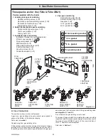
12.3 Initial Lighting
- Adjust heating temperature to maximum, refer to User Controls
and Lighting.
- Check that any system controls, if fitted, are calling for heat
(set room thermostat to maximum).
- Allow the temperature to rise to the maximum value, with all
radiator valves open. The temperature rise will cause release of
the gases contained in the water of the central heating system.
- Gases driven towards the boiler will be automatically released
through the automatic air vent. The gases trapped at the highest
point of the system must be released by bleeding the radiators.
- Check the burner gas rate required, ten minutes after lighting.
Refer to Data Label on the inner casing panel. Should there be
any doubt about the gas rate it should be checked at the meter.
The approximate gas rate is for guidance only
(MAX.) 2.7 m
3
/h (97 ft
3
/h)
(MIN.) 0.5 m
3
/h (19 ft
3
/h)
On reaching maximum temperature, the boiler should be turned
off and the system drained as rapidly as possible whilst still hot.
- Refill system to a pressure of 1.0 bar and vent as before.
- Restart boiler and operate until a maximum temperature is
reached. Shut down boiler and vent heating system. If necessary,
top up heating system and make sure that a pressure of at least
1 bar is indicated when system is COLD.
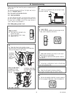
12.4 DHW Pre-heat Function
There is a domestic hot water pre-heat function which is factory
set to on.
With pre-heat "On" the boiler will light every hour, or after a
demand, to reheat the primary domestic hot water circuit if
necessary.
The pre-heat function can be turned off if required but the DHW
response will be affected.
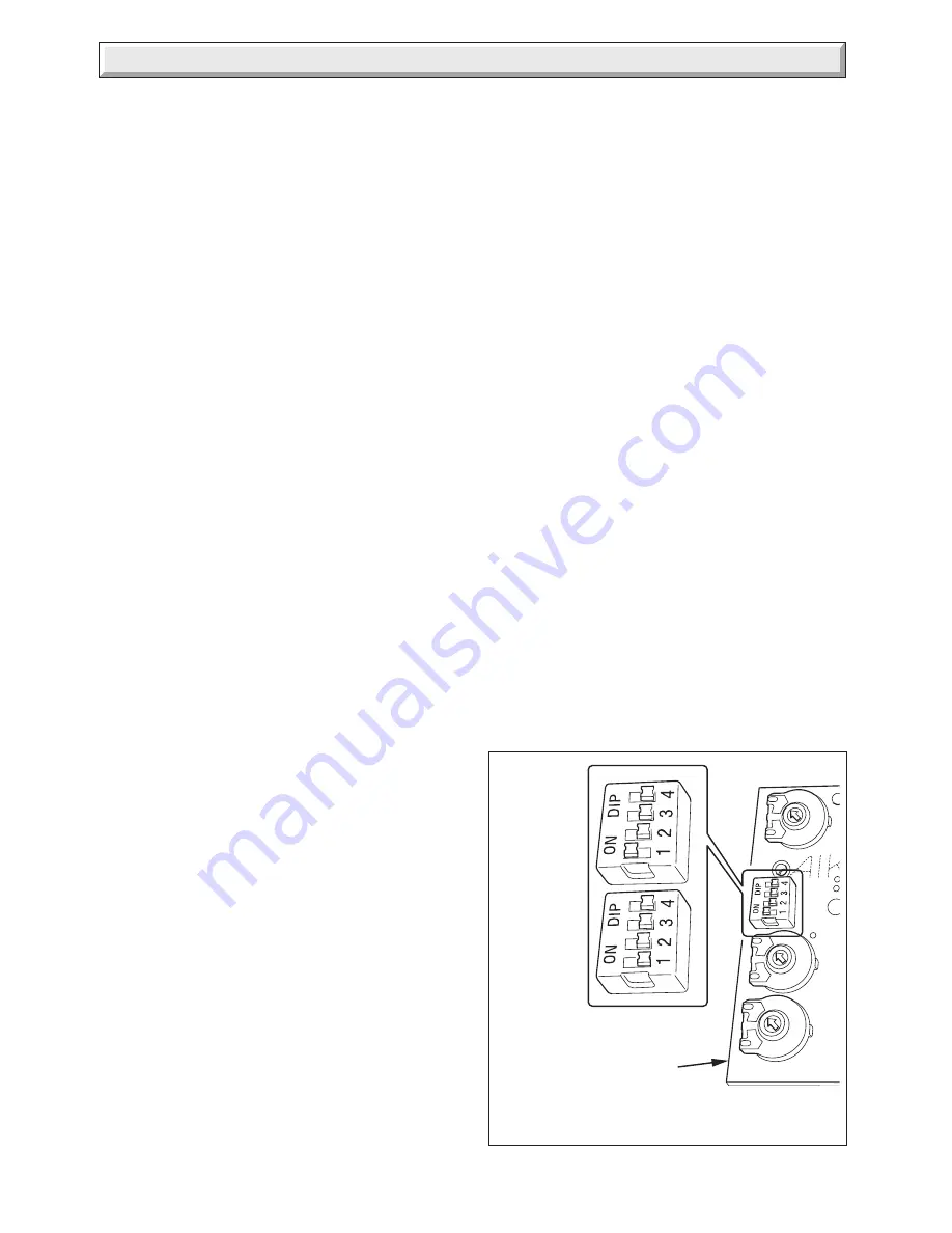
To turn the pre-heat off, slide dip switch 1 to the 'ON' position.
Refer to
section 11.3
to gain access to the user interface PCB.
On completion adjust the temperature control and any system
controls to their required settings. In addition it is neccessary to
complete the "Benchmark" logbook.
For IE, it is neccessary to complete a "Declaration of Conformity"
to indicate compliance to I.S.813. An example of this is given in
the current edition of I.S.813.
Testing Flue Gases:
If any doubt exists that the flue products
are not exhausting correctly, investigate by use of a gas
analyser (FGA).
12 Commissioning
Diagram 12.1
12.5 Instruct the User
Instruct and demonstrate the lighting procedure and advise the
user on the safe and efficient operation of the boiler.
Instruct on and demonstrate the operation of any heating
system controls.
Advise the user on the use and maintenance of any scale
reducer and pass on any relevant instructional documents.
Advise that to ensure the continued efficient and safe operation
of the boiler it is recommended that it is checked and serviced
at regular intervals. The frequency of servicing will depend upon
the installation conditions and usage, but in general, once a
year should be enough.
Draw attention, if applicable, to the current issue of the Gas
Safety (Installation and Use) Regulations, Section 35, which
imposes a duty of care on all persons who let out any property
containing a gas appliance in the U.K.
The user shall not interfere with or adjust sealed components.
It is the Law that any servicing is carried out by a
competent
person
.
Advise the user of the precautions necessary to prevent damage
to the system, boiler and the building, in the event of the heating
system being out of use during frost or freezing conditions.
Advise the user that the permanent mains electrical supply
SHOULD NOT be switched off, as the built in frost protection
and pump saver (anti sieze) program would not be operable.
Reminder, leave these instructions and the 'Benchmark' logbook
with the user.
For IE, it is necessary to complete a "Declaration of Conformity"
to indicate compliance to I.S.813. An example of this is given in
the current edition of I.S.813.
DIP SWITCH
preheat OFF
USER
INTERFACE
PCB
12186
DIP SWITCH
preheat ON
Summary of Contents for EnviroPlus F24e
Page 18: ...18 2000225294A Diagram 5 1 11907 5 Boiler Schematic F24e F28e ONLY ...
Page 19: ...19 2000225294A 5 Boiler Schematic Diagram 5 1a 12248 BYPASS F28e SB ONLY ...
Page 49: ...49 2000225294A 14 Fault Finding 12410 Diagram 14 4 ...
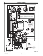
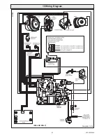
Page 51: ...51 2000225294A 15 Wiring Diagram Diagram 15 1a 12240 F28e SB ONLY ...

