background image

34

2000225294A

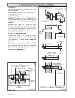
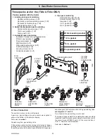
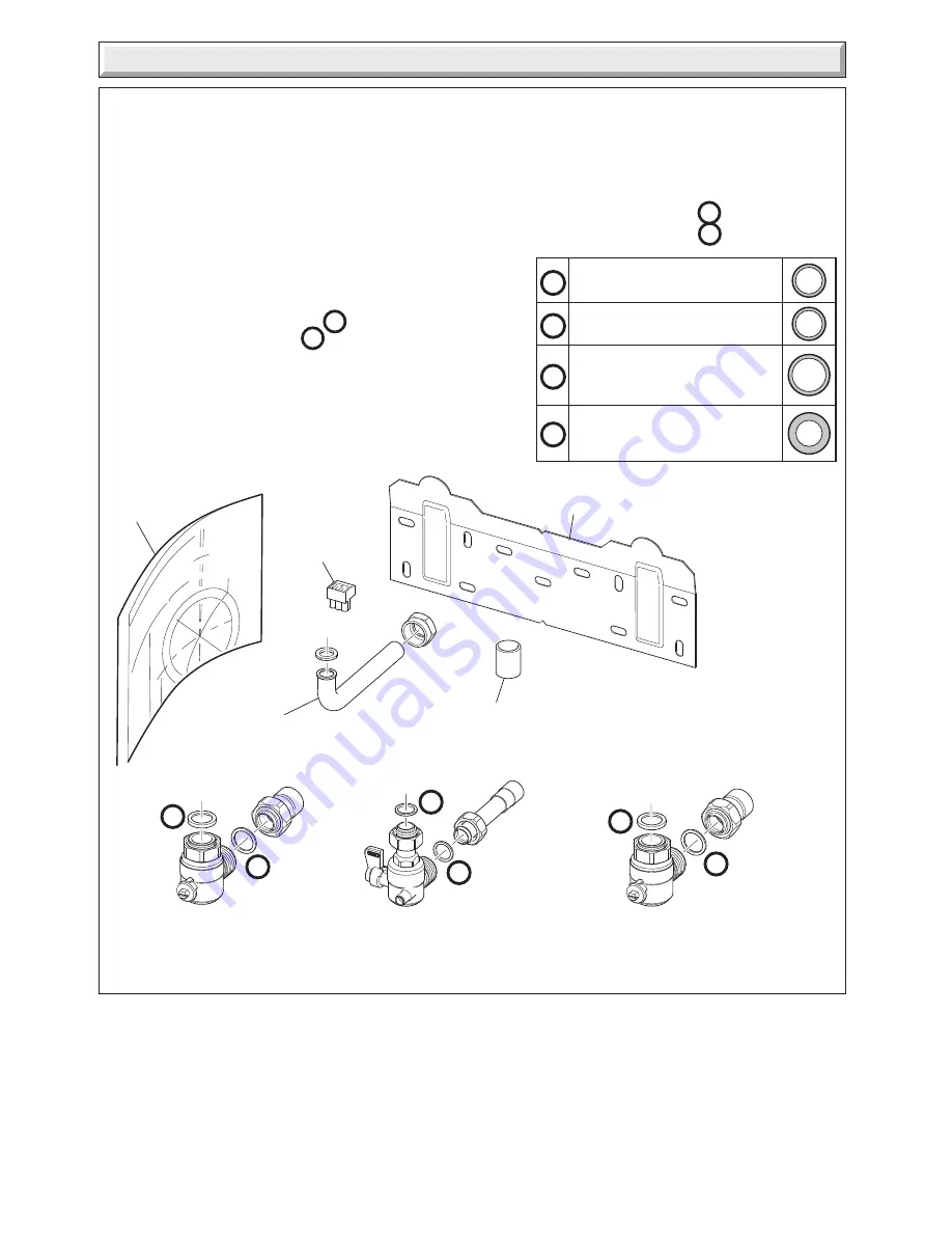
9  Gas/Water Connections

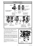
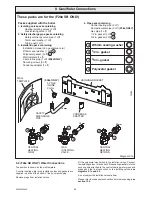
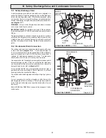
9.2 (F28e SB ONLY) Water Connections

The position is shown on the wall template.

A central heating water pipe, isolation valves and gaskets are
supplied in packs at the bottom of the boiler packaging.

Remove plugs from isolation valves.

Diagram 9.1a

12263

These packs are for the (F28e SB ONLY)

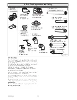
Fit the polyacetal washers onto the isolation valves. Connect
the isolating valves  to the boiler. Fit the sealing washers into the
securing nuts attached to the  central heating water pipes and
make good the final connection to the isolating valves, 

see

diagrams 9.1a and 9.2.

Do not subject the isolation valves to heat.

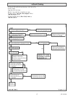
Please refer to condensate connection before proceeding, 

see

section 10.2.

(F28e ONLY)

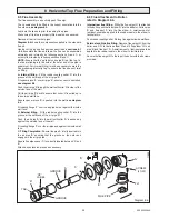
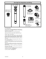
Packs supplied with the boiler

1. Isolating valve pack containing

Heating isolating valves (2 off)
Gas isolating valve (1 off)

2. Safety discharge pipe pack containing

Safety discharge valve pipe (1 off)
15mm seal washer (1 off)
Tubing nut (1 off)

3. Installation pack containing

Installation manual (inc. guarantee card)
Ø15mm seal washer (1 off)   

a

Polyacetal gasket (2 off)  

d

Wall template (1 off)
3 pole inline plug (1 off) 

(F28e ONLY)

Securing screws (3 off)
Condense adapter (1 off)

4. Pipe pack containing

Central heating pipe (2 off)
Domestic water pipe (2 off) 

(F28e ONLY)

Gas pipe (1 off)
1/2 in. gasket (3 off)  

b

3/4 in. gasket (2 off)  

c

15mm

15mm

b   1/2 in. gasket

a   Ø15mm sealing washer

c   3/4 in. gasket

d   Polyacetal gasket

22mm

22mm

HANGING BRACKET

WALL
TEMPLATE

CENTRAL
HEATING
FLOW

GAS
ISOLATING
VALVE

SAFETY
DISCHARGE
PIPE

CENTRAL
HEATING
RETURN

3 POLE
INLINE
PLUG

c

c

d

d

a

b

CONDENSE
ADAPTER

Summary of Contents for EnviroPlus F24e

Page 1: ...rvicing 11915 Saunier Duval Nottingham Road Belper Derbyshire DE56 1JT www saunier duval co uk HIGH EFFICIENCY CONDENSING COMBINATION BOILER G C No 47 920 39 F28e HIGH EFFICIENCY CONDENSING SYSTEM BOILER G C No 41 920 37 F28e SB HIGH EFFICIENCY CONDENSING COMBINATION BOILER G C No 47 920 45 F24e ...

Page 2: ...recommend regular servicing of your gas appliance but where the condition is not met any chargeable spare parts or components issued within the applicable guarantee period still benefit from a 12 month warranty from the date of issue by the manufacturer We recommend you complete and return as soon as possible your guarantee registration return literature supplied in the document envelope If your g...

Page 3: ... 8 26 Twin Flue Preparation and Fitting 8 28 Gas Water Connections 9 32 Safety Discharge Valve and Condensate Connections 10 35 Electrical Connections 11 37 Commissioning 12 39 Servicing 13 41 Fault Finding 14 46 Wiring Diagram 15 50 51 Replacement of Parts 16 52 Spare Parts 17 63 CONTENTS DESCRIPTION SECTION PAGE No SERVICING INSTRUCTIONS INSTALLATION INSTRUCTIONS INSTRUCTIONS FOR THE USER Conten...

Page 4: ... and preferably adjacent to the appliance It should be identified as to its use Alternatively connection can be made through an unswitched shuttered socket and 3A fused 3 pin plug both to the current issue of BS 1363 may be used provided they are not used in a room containing a bath or shower Wiring to the boiler must be PVC 85O C insulated cable not less than 0 75mm2 24 0 20mm Gas Category The bo...

Page 5: ... lean forward sideways Clear the route before attempting the lift If removing boiler from truck straddle the load and tilt forwards to facilitate secure grip Ensure safe lifting techniques are used keep back straight bend using legs Do not twist reposition feet instead Take care to avoid trip hazards slippery orwetsurfacesandwhenclimbingstepsandstairs Alwaysuse assistance if required Carriage of c...

Page 6: ...during 2 person lifts to ensure equal spread of weight of load If 1 person positioning onto bracket recommend obtain firm grip supporting base of boiler Ensure safe lifting techniques are used keep back straight bend using legs when lifting load from floor level Do not twist reposition feet instead Keep boiler as close as possible to body throughout lift to minimise strain on back Always use assis...

Page 7: ...d economical use of your boiler Note The boiler serial number is marked on the data label attached to the inner casing panel The Controls lighting section describes how to safely use the boiler User Instructions Appliance Safety Devices Accessories A range of accessories are available For further information contact your supplier Overheating safety In the event of the boiler overheating the safety...

Page 8: ... installation servicing company as draining refilling and pressurising MUST be carried out by a competent person User Instructions Maintenance and Servicing Draining and filling Caution The boiler is installed as part of a sealed system which must only be drained and filled by a competent person If the boiler is to be out of use for any long periods during severe weather conditions it is recommend...

Page 9: ...AL HEATING CONTROL 1 Turn the central heating knob ON the lighting sequence will begin the running lamp will illuminate green to indicate the boiler has lit the system temperature will now be displayed instead of system pressure The temperature of the central heating water can be adjusted by turning the central heating control knob to desired setting between 1 Min and 5 Max or frost protection 5 M...

Page 10: ...ET F28e SB ONLY This sealed water system must be filled and pressurised by a competent person YOU MUST CONTACT YOUR INSTALLER OR SAUNIER DUVAL S OWN SERVICE ORGANISATION USING THE TELEPHONE NUMBER ON THE INSIDE FRONT COVER OF THIS BOOKLET To Turn the Boiler Off There is a mains reset switch on the right hand side of the controls fascia which will isolate the boiler However it is preferable to leav...

Page 11: ...set the display to the correct time in twenty four hour format for example 1300 for 1pm see diagram 3 Helpful hint The and buttons are used to change the times Press and release for small changes hold the button down and the time will change quickly To use the internal factory set programmes place the slide switch to the RUN position The display will show the current time and the ON or OFF symbol ...

Page 12: ...am 7 The series of dashes are between times 23 59 and 0 00 Helpful Hint If you get confused and wish to start again press the Reset res button and the programmer will revert to the internal factory set programme You can now reset the current time and start again To check the programme ON and OFF times The programmed ON and OFF times can be checked at any time by moving the slide switch from RUN to...

Page 13: ...ight boiler only F24e 47 kg F28e 47 kg F28e SB 42 kg Gross lift weight boiler and packaging F24e 52 kg F28e 52 kg F28e SB 47 kg 12179 FLOW RETURN D H W OUT D C W IN GAS The boiler and fittings pack are delivered in one carton The flue is supplied separately ...

Page 14: ...TU H Heat output max GROSS P 25 1 kW 85 641 BTU H Heat output min GROSS P 4 9 kW 16 719 BTU H Maximum hot water temperature 63 C Minimum hot water temperature 38 C Specific flow rate for 35 C temp rise 10 l min Threshold flow rate 1 5 l min Maximum supply pressure 10 bar Minimum supply pressure 1 bar Combustion Products outlet diameter 60 mm Fresh air inlet diameter 100 mm Combustion products valu...

Page 15: ...ard Code of Practice In IE the installation must be carried out by a competent person and installed in accordance with the current edition of I S 813 Domestic Gas Installations the current Building Regulations and reference should be made to the current ETCI rules for Electrical Installation In GB the following Codes of Practice apply BS4814 BS6798 BS5440 Part 1 and 2 BS5546 Part 1 BS5449 BS6891 B...

Page 16: ...he Water regulations your attention is drawn to TheWaterRegulationsguidepublishedbytheWaterRegulations Advisory Service WRAS gives full details of the requirements In IE the requirements given in the current edition of I S 813 DomesticGasInstallations andthecurrentBuildingRegulations must be followed 3 1 Bypass NOTE Allsystemsmusthaveatleastoneradiatornotfittedwith a thermostatic valve The boiler ...

Page 17: ...r system Unnecessary pressure losses should be avoided Provision shall be made for a drain valve at the lowest point of the system The boiler will operate with a supply pressure of 0 6 bar but under reduced flow rate In these circumstances the filling loop will not pressurise the boiler Best operating comfort will be obtained from a supply pressure of 1 bar 4 1 Hard Water Areas In areas where the ...

Page 18: ...18 2000225294A Diagram 5 1 11907 5 Boiler Schematic F24e F28e ONLY ...

Page 19: ...19 2000225294A 5 Boiler Schematic Diagram 5 1a 12248 BYPASS F28e SB ONLY ...

Page 20: ...ing boiler some pluming may occur from the flue outlet This should be taken into consideration when selecting the position for the terminal Carports or similar extensions of a roof only or a roof and one wall requirespecialconsiderationwithrespecttoanyopenings doors vents or windows under the roof Care is required to protect the roof if made of plastic sheeting If the carport comprises of a roof a...

Page 21: ... Kent TN9 1RA 6 4 Flue options There are various flue systems to choose from as follows Horizontal top flue Flue Extension 90O Vertical flue Flue Extensions 45O and 90O Twin flue Flue Extensions 45O and 90O For detailed information refer to flue options guide This is available from your nearest stockist 6 5 Timber Frame Buildings If the boiler is to be installed in a timber frame building it shoul...

Page 22: ...ameter core drill can be used For installations with internal access only a 125mm diameter core drill should be used Diagram 7 2 When using extension pipes with the horizontal rear flue a core drill size of 125mm should be used to allow the extension pieces to slope at 35mm metre 2 5o towards the boiler For extended side flues the flue hole centre should be determinedbyextendingthedashedinclinedli...

Page 23: ...l face is not practicable 8 1 Flue Length All dimensions are in mm For a rear flue measure the distance from the outside wall face to the boiler mounting wall Check that the flue length will be suitable see diagram 8 1 for a standard flue system For a side flue measure the distance from the outside wall face to the flue outlet centre line of the boiler Check that the flue length will be suitable s...

Page 24: ... flue to length Make sure that the flue duct groove is engaged on air duct tab and is pushed fully into the air duct When fully engaged the measurment at the end of the terminal will be 65mm Then cut cutting square and removing any burrs see diagram 8 5 8 4 Side Flue With Extensions Fit the flue spigot H supplied with the boiler with the three securing screws to the top of the boiler Fit the flue ...

Page 25: ...f the outside face of the wall Pull the air pipe B back to ensure that collar D is pulled up to the outside wall face Ensure spacer piece E is pushed into the wall see diagram 8 4 Fit sealing flange F over the air pipe but not against the inside wall face B External fitting Fit the rubber sealing collar D into the groove at the outer end of the air pipe B Push the air pipe B into the wall until co...

Page 26: ...all burrs from cut pipes You can either cut the 1 metre extension pipes cutting equal amounts off both the air duct and flue duct cut the plain end not the flared end where the sealing rings are fitted or use the 400mm 500mm metre adjustable pipe to make up the required flue length Note The 400mm 500mm telescopic pipe if used is fitted to the top outlet of the appliance Your selected flue arrangem...

Page 27: ... sure a weather proof seal is made in accordance with good building practice FLAT ROOF FLASHING PITCHED ROOF FLASHING VERTICAL ROOF TERMINAL 1 METRE EXTENSION 1 METRE EXTENSION VERTICAL ROOF TERMINAL 12196 Diagram 8 8 TERMINAL 1 METRE EXTENSION 1x90 or 2x45 ELBOWS 1 METRE EXTENSION 1x90 or 2x45 ELBOWS 400 500mm ADJUSTABLE PIPE FIXING BRACKETS 12192 VERTICAL FLUE ADAPTOR 565 100 730 1195 140 445 ...

Page 28: ... fixing bracket to be used for every metre of flue pipe used The terminal should be positioned as to cause the least problem with the dispersal of products of combustion and any pluming that may occur The use of weather collars are the preferred method when installing the roof terminal Diagram 8 10 12209 TWIN FLUE ADAPTOR KIT Pt No A2025000 TWIN PIPE TO CONCENTRIC ADAPTOR Pt No 08511800 SINGLE PIP...

Page 29: ...1 METRE EXTENSION 45 ELBOW TWIN FLUE ADAPTOR TWIN FLUE ADAPTOR SUPPORT BRACKET 12199 900 92 40 92 50 50 50 50 1000 An Example Twin Flue Installation The flue assembly is an entirely push fit design see diagram 8 11 Fitting Twin Flue Adaptor see diagram 8 12 Fitting Twin Flue Terminals see diagram 8 13 Fitting Concentric Horizontal Terminal see diagram 8 14 Fitting Vertical Roof Terminal see diagra...

Page 30: ...agram 8 13 Diagram 8 14 90 ELBOW 90 ELBOW SEALING COLLARS SEALING COLLARS AIR DUCT TERMINAL FLUE DUCT TERMINAL 1 METRE EXTENSION cut to fit EXTERNAL SEALING COLLAR 1 METRE EXTENSION CONCENTRIC ADAPTOR CONCENTRIC HORIZONTAL TERMINAL INTERNAL SEALING COLLAR 11742 ...

Page 31: ...ENTRIC ADAPTOR 1 METRE EXTENSION Fit flat roof or pitched weather collar onto vertical roof terminal Make sure a weather proof seal is made in accordance with good building practice FLAT ROOF FLASHING PITCHED ROOF FLASHING VERTICAL ROOF TERMINAL CONCENTRIC ADAPTOR CONCENTRIC ADAPTOR SINGLE PIPE ADAPTOR SINGLE PIPE ADAPTOR Diagram 8 16 VERTICAL ROOF TERMINAL 12204 11743 565 100 730 1195 140 445 ...

Page 32: ...e gas isolating valve see diagrams 9 1 and 9 2 Do not subject the gas isolating valve to heat The whole of the gas installation including the meter should be inspected tested for soundness and purged in accordance with the current issue of BS6891 and in IE the current edition of I S 813 Domestic Gas Installations Refer also to Section 1 These packs are for the F24e F28e ONLY Packs supplied with th...

Page 33: ...nd gaskets are supplied in packs at the bottom of the boiler packaging Remove plugs from isolation valves and domestic hot water elbow Fitthepolyacetalwashersontotheisolationvalvesanddomestic hot water elbow Connect the isolating valves and domestic hot water elbow to the boiler Fit the sealing washers into the securing nuts attached to the central heating and domestic water pipes and make good th...

Page 34: ...eding see section 10 2 F28e ONLY Packs supplied with the boiler 1 Isolating valve pack containing Heating isolating valves 2 off Gas isolating valve 1 off 2 Safety discharge pipe pack containing Safety discharge valve pipe 1 off 15mm seal washer 1 off Tubing nut 1 off 3 Installation pack containing Installation manual inc guarantee card Ø15mm seal washer 1 off a Polyacetal gasket 2 off d Wall temp...

Page 35: ...asticoverflow pipeissuppliedlooseintheinstallation pack and should be used to fit to the drain connection if required to discharge condensate to a drain The drain pipe should have a fall of a least 2 5o away from the boiler Condensateshould ifpossiblebedischargedintothehousehold internal drainage system If this is not practicable discharge can be allowed into the external household drains or a pur...

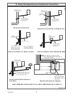
Page 36: ...NCE NOTE FOR EXTENDED PIPE RUNS 32MM DIA PIPE SHOULD BE USED 2 5 FALL o 25MM CEMENT MORTAR SEALING BOTTOM OF TUBE SEALED 100MM PLASTIC TUBE 300MM HOLE DEPTH 400MM 2 ROWS OF 3 x 12MM HOLES AT 25MM CENTRES 50MM FROM BOTTOM OF TUBE HOLES TO FACE AWAY FROM HOUSE External Soil and Vent Pipe or Rainwater Pipe Internal Soil and Vent Pipe External Termination into Soakaway Internal Termination Downstream ...

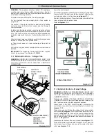
Page 37: ... REAR COVER SECURING SCREW 3 VOLTAGE FREE HEATING CONTROLS CONNECTION WIRE LINK E Diagram 11 1 12224 11985 RETAINING SLOTS RETAINING CORD Lower the control panel This boiler will operate continuously on heating as supplied if the wire link E fitted between the two terminals of the heating controls connection is left in place see diagram 11 1 System heating controls e g Room thermostat should be fi...

Page 38: ...FACE Route the external controls cable through to the rear of the control panel where the other cables exit External controls should be fitted in accordance with the rules in force Refer to Section 15 wiring diagram 11 3 Electrical Connections Testing Carry out preliminary electrical system checks as below 1 Test insulation resistance to earth of mains cables 2 Test the earth continuity and short ...

Page 39: ...pen the three boiler isolating valves The slot of the screw corresponds to flow direction Turn anti clockwise to open fully 3 4 Make sure that The boiler is connected to the electrical supply The gas service cock is open Switch OFF 0 Undo cap on automatic air vent on top of boiler and leave undone 6 7 Leave cap on automatic air vent on top of boiler open see procedure 3 Flush the domestic hot wate...

Page 40: ...gs In addition it is neccessary to complete the Benchmark logbook ForIE itisneccessarytocompletea DeclarationofConformity to indicate compliance to I S 813 An example of this is given in the current edition of I S 813 Testing Flue Gases If any doubt exists that the flue products are not exhausting correctly investigate by use of a gas analyser FGA 12 Commissioning Diagram 12 1 12 5 Instruct the Us...

Page 41: ...ng panels only Unless stated otherwise any part removed during servicing should be replaced in the reverse order to removal Servicing should always include the removal of any debris from the condensate pipe and siphon refer to Section 13 5 After completing any servicing of gas carrying components ALWAYS test for gas soundness and carry out a functional test of the controls Testing Flue Gases If an...

Page 42: ... any signs of damage The burner can be cleaned if necessary by washing in warm soapy water and rinsing with clean water DO NOT use wire or sharp instruments to clean the holes of the burner Examine the fan seal and replace if necessary IMPORTANT Care should be taken when inserting the burner into the heat exchanger chamber and replacing the gas valve fan and silencer assembly The fan seal must be ...

Page 43: ...fasciaandhingeitdowntorevealthepotentiometersontherear of the User interface see diagrams 13 7 and 13 8 Take care not to allow the fascia to drop down and damage the wiring Turn on the electrical supply Ensure external controls are calling for heat The boiler should fire automatically Allow the boiler to fire for a minimum of 60 seconds and then usinganelectricalscrewdriver rotatetheservicepotenti...

Page 44: ...ng and remove the filter to clean or renew if necessary see diagram 13 10 Replace the filter into its housing and replace plug Open the cold water isolating valve and test the Domestic Hot Water circuit for soundness Check for leaks 13 8 F24e F28e ONLY Domestic Cold Water Inlet Filter If the water flow rate through the appliance has reduced it may be necessary to clean or replace the filter Turn o...

Page 45: ...acing parts open the cold water isolation valve and slowly open a hot water tap to remove air Close the hot water tap and check for any leaks 13 11 Inner Casing Panel Seal Check Check the condition of the seal replace as required To replace remove the old seal thoroughly clean the casing sufaces Fit the new seal it is supplied to the correct length see diagram 13 13 13 12 Heat exchanger Only clean...

Page 46: ...al supply and water isolation valves are open WARNING Always isolate the boiler from the electrical supply before carrying out any electrical replacement work Always check for gas soundness after any service work Shouldtherebeanydoubtaboutthevoltagesupplytoanyofthe components it is possible to carry out a simple electrical test to ensure all is operational in that area F24e F28e ONLY ...

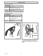
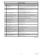
Page 47: ...l Box PCB as follows Hinge down the control box Remove Torx screws and unhook the rear panel For layout of PCB see F24e F28e diagram 15 1 or F28e SB diagram 15 1a To check components see F24e F28e Table 1 or F28e SB Table 1a 14 Fault Finding Diagram 14 1a 11988 F28e SB ONLY ...

Page 48: ...R 12216 OVERHEAT RESET BUTTON F28e SB ONLY Table 1a COMPONENT C H thermistor 10K Ω 25 C Fan 24V DC accross terminals on fan 40V dc in standby mode see diagram 14 2 Check 3 15 AT fuse on DC fan supply Gas Valve 24VDC 55 Ω 14 1 Overheat Thermistor reset button see diagram 14 3 Positioned at the rear left under the fan ...

Page 49: ...49 2000225294A 14 Fault Finding 12410 Diagram 14 4 ...

Page 50: ...30V SWITCHED LIVE FROM OPTIONAL FROST STAT REMOVE THE LINK IF FITTING VOLTAGE FREE OR 230V SYSTEM CONTROLS IF THE LINK IS NOT REMOVED THE BOILER WILL RUN CONTINUOUSLY MAINS VOLTAGE HEATING CONTROLS PLUG VOLTAGE FREE HEATING CONTROLS PLUG LINK REMOVE VOLTAGE FREE LINK 11919a F24E F28e ONLY ...

Page 51: ...51 2000225294A 15 Wiring Diagram Diagram 15 1a 12240 F28e SB ONLY ...

Page 52: ... ignition electrode lead and two securing screws Withdraw the ignition electrode carefully from the combustion chamber 16 3 Igniter Unit For access refer to section 16 1 Remove ignition lead and electrical connection then remove igniter unit by removing the securing screw see diagram 16 1 16 4 Ignition Lead For access refer to section 16 1 Refer to diagrams 13 3 and 16 1 Pull the ignition electrod...

Page 53: ...on 13 3 for removal of the fan gas control valve and silencer assembly Remove the gas control valve and plate which is held by the three plate securing screws see diagram 16 4 Unclip silencer box from silencer cover and remove the venturi plate secured with three screws see diagram 16 5 Check O ring and fan seal and replace if necessary 16 8 Burner For access refer to section 16 1 Refer to section...

Page 54: ... exchanger from pipes When replacing water connections fit the O rings onto the copper pipe tails care should be taken not to damage O rings when securing with retaining clips Refill vent and pressurise the boiler 16 10 Pump head only For access refer to section 16 1 Drain the boiler heating circuit see section 13 9 Make sure that the filling loop valves are closed then proceed as Section 16 19 F2...

Page 55: ...f expansion vessel see diagram 16 7 Refer to diagram 16 8 Undo the coupling at the base of the vessel Remove the securing screws on the top panel of the boiler Remove support bracket Draw the vessel up and forward carefully easing the plate to plate pipes clear and remove Fit the replacement unit Fit a new gasket between the expansion vessel and coupling Refill vent and pressurise the boiler Check...

Page 56: ...Remove the electrical connections from the thermistor Remove the thermistor and retaining clip Fit the replacement thermistor using the heat sink compound supplied Note When reconnecting electrical connections polarity is not important Carry out a functional test of the controls 16 14 Central Heating Flow Thermistor For access refer to section 16 1 Refer to diagram 16 11 Remove the electrical conn...

Page 57: ... Overheat Cutoff Thermistor For access refer to section 16 1 Note It may be necessary to remove transformer refer to section 16 5 Refer to diagram 16 13 Positioned at the rear left under the fan Remove the electrical connections from the overheat cutoff thermistor Remove the thermistor and retaining clip from the flow pipe Fit the replacement thermistor using the heat sink compound supplied Note W...

Page 58: ...ing Loop Tubes Assembly For access refer to section 16 1 Refer to diagram 16 16 Remove the retaining clips to remove the reduced pressure zone valve and filling loop tubes assembly Fit new O rings Replace the reduced pressure zone valve and filling loop tubes assembly refill vent and pressurise the boiler Check for leaks 16 20 F24e F28e ONLY Filling Loop Valve For access refer to section 16 1 Refe...

Page 59: ...ump head removed as Section 16 10 Remove the pipe retaining clip and disconnect the two union connections Remove the three way valve Refer to diagram 16 18 Disconnect the electrical lead by pushing up retaining tab to withdraw the lead plug Remove the retaining clip to remove the low water pressure sensor Fit new O ring Fit the new pressure sensor Refill vent and pressurise the boiler Check for le...

Page 60: ... 16 1 Remove electrical plug Remove the two securing screws Withdraw the board see diagram 16 21 When replacing the board refer to instructions supplied with replacement PCB on setting it up 16 30 F24e F28e ONLY Three Way Valve PCB Refer to section 16 1 for access Drop down control panel and undo the three screws securing rear cover and lift up see relevant part of diagram 11 1 Remove electrical p...

Page 61: ...rom the mainPCB and replace fuse see diagram 16 22 PCB Transformer For access refer to section 16 1 Refer to diagram 16 2 and wiring diagrams section 15 Replace fuse 16 34 230V Controls Option For access refer to section 16 1 Gain access to the 230v controls optionPCB by unclipping the control panel interface and carefully lowering forward see diagram 11 3 Disconnect the electrical connection from...

Page 62: ...8eONLY Removethedomestichotwaterpipefrom the boiler at the domestic hot water connector and the electrical connections to the thermistor F24E F28e ONLY Remove the domestic cold water supply pipe from the boiler Disconnecttheoverheatcutoffthermistorelectricalconnections see diagram 16 13 Remove the central heating flow pipe from the boiler Remove the syphon adapter see diagram 16 24 Remove the pump...

Page 63: ...low Thermistor E84003 11a 802250 D H W Thermistor F24e F28e H17 827 12 802265 Gas control valve H17 619 13 802266 Flow Sensor H17 721 14 801655 Igniter Unit E84015 15 2000802120 230V Controls Option PCB H19 989 16 802259 Main PCB H17 679 17 802226 Pump H17 664 18 802260 Interface Board F24e F28e H17 746 18 802281 Interface Board F28e SB H17 713 19 2000802204 Fan H17 618 20 S801039 Burner F24e E242...

Page 64: ...294A Because of our constant endeavour for improvement details may vary slightly from those shown in these instructions Diagram 17 1 1 2 3 4 6 7 8 9 5 10 13 12 14 15 17 16 19 18 20 11 and 11a 11922 17 Spare Parts ...

Reviews: