35
2000225294A
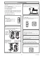
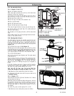
10.1 Safety Discharge Valve
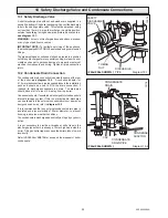
A short discharge pipe with nut and washer are supplied in a
pack at the bottom of the boiler packaging. Connect the discharge
tube to the heating safety valve. This must be extended, using
not less than 15mm o.d. pipe, to discharge, in a visible position,
outside the building, facing downwards, preferably over a drain,
see diagram 10.1.
WARNING:
it must not discharge above an entrance, window
or any type of public access area.
IMPORTANT NOTE:
To facilitate servicing of the appliance,
the discharge pipe MUST ONLY be extended using compression
fittings.
The pipe must have a continuous fall and be routed to a position
so that any discharge of water, possibly boiling, or steam cannot
create any danger to persons, damage to property or external
electrical components and wiring. Tighten all pipe connection
joints.
10.2 Condensate Drain Connection
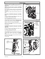
The condensate drain connection is beside the pump at the rear
of the boiler,
see diagram 10.2
. A condense adaptor for
21.5mm plastic overflow pipe is supplied loose in the installation
pack and should be used to fit to the drain connection, if
required, to discharge condensate to a drain. The drain pipe
should have a fall of a least 2.5
o
away from the boiler.
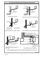
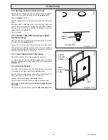
Condensate should, if possible be discharged into the household
internal drainage system. If this is not practicable, discharge
can be allowed into the external household drains or a purpose
designed soak away, refer to
diagram 10.3
.
It is recommended that any external condensate drain pipe is
insulated and also preferably of 32mm diameter, to prevent
freezing in adverse weather conditions.
The condensate is discharged periodically in 'slugs' by syphonic
action.
It is not necessary to provide air breaks or extra traps in the
discharge pipe as there is already a 75mm. high trap inside the
boiler. Fitting an extra trap may cause the boiler siphon to work
incorrectly.
Refer to BS5546 or BS6798 for advice on the disposal of boiler
condensate.
Diagram 10.2
CAP
CONDENSATE
DRAIN
CONDENSATE
DRAIN PIPE
10 Safety Discharge Valve and Condensate Connections
12178
Diagram 10.1
SAFETY
DISCHARGE
VALVE
TUBING
NUT
12214
DISCHARGE
PIPE
(F24e/F28e SHOWN )
(F24e/F28e SHOWN )
CONDENSE
ADAPTOR
Summary of Contents for EnviroPlus F24e
Page 18: ...18 2000225294A Diagram 5 1 11907 5 Boiler Schematic F24e F28e ONLY ...
Page 19: ...19 2000225294A 5 Boiler Schematic Diagram 5 1a 12248 BYPASS F28e SB ONLY ...
Page 49: ...49 2000225294A 14 Fault Finding 12410 Diagram 14 4 ...
Page 51: ...51 2000225294A 15 Wiring Diagram Diagram 15 1a 12240 F28e SB ONLY ...

