54
2000225294A
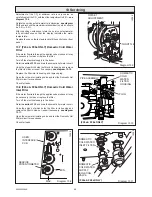
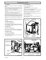
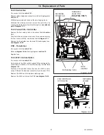
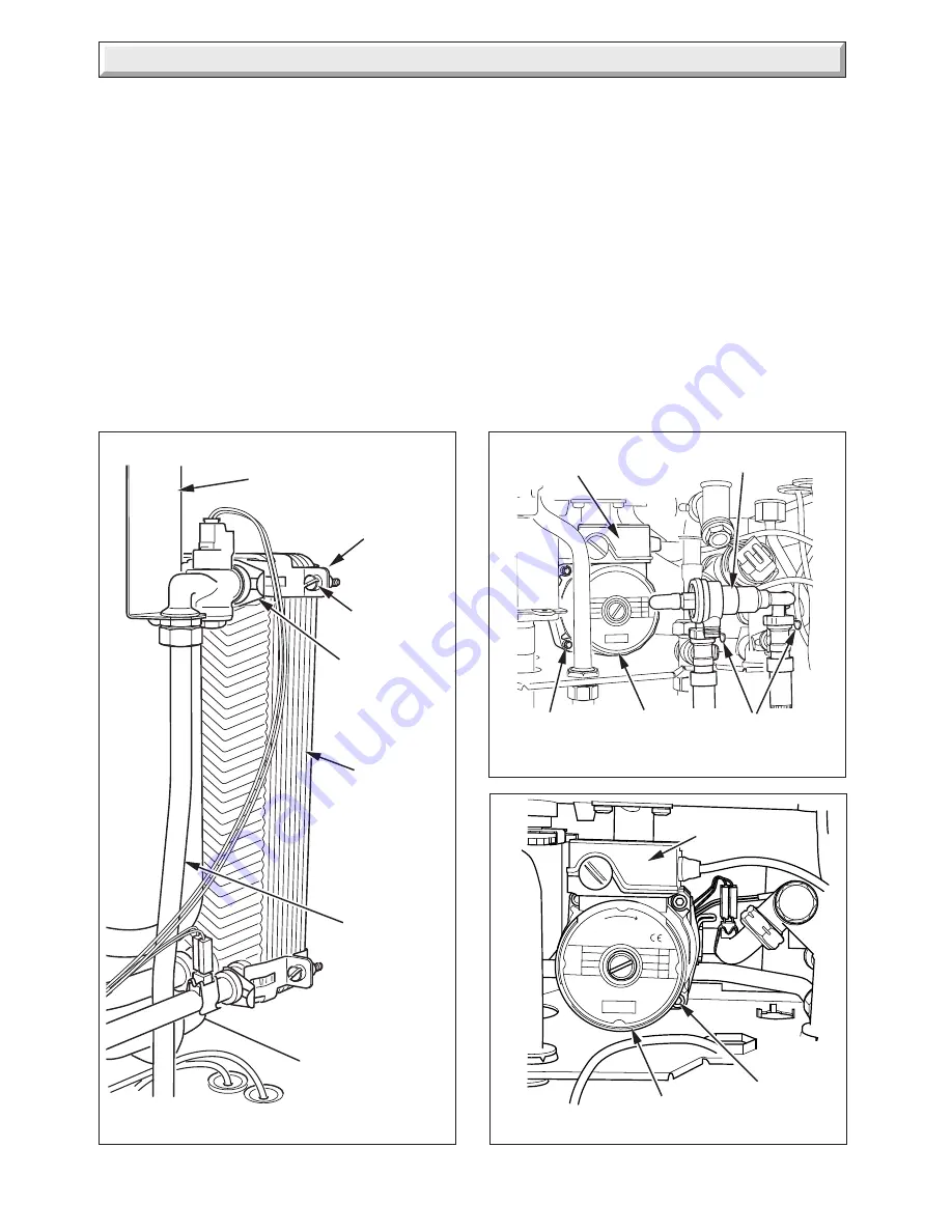
Diagram 16.6
RETAINING
CLIP (4 OFF)
PLATE TO
PLATE HEAT
EXCHANGER
SUPPORT
BRACKET
16 Replacement of Parts
COLD WATER
INLET PIPE
12187
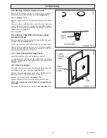
Diagram 16.7
REDUCED PRESSURE
ZONE VALVE
CABLE
COVER
CAP HEAD
SCREW (4)
PUMP
HEAD
12212
SECURING
CLIPS
(F24e/F28e ONLY)
(F24e/F28e ONLY)
(F28e SB ONLY)
Diagram 16.7a
CABLE
COVER
CAP HEAD
SCREW (4)
PUMP HEAD
12244
16.9 (F24e/F28e ONLY) Plate to Plate Heat
Exchanger
Drain the heating circuit,
see section 13.9.
Drain the hot water circuit,
see section 13.10.
Release Rhd. side panel to gain increased access.
Remove retaining clips from water connections,
see diagram
16.6.
Remove the plate to plate heat exchanger from pipes.
When replacing water connections fit the 'O' rings onto the
copper pipe tails, care should be taken not to damage 'O' rings,
when securing with retaining clips.
Refill, vent and pressurise the boiler.
16.10 Pump (head only)
For access,
refer to section 16.1.
Drain the boiler heating circuit,
see section 13.9.
Make sure that the filling loop valves are closed, then proceed
as
Section 16.19 (F24e or F28e only).
Refer to
diagram 16.7.
Remove the four cap head screws.
Carefully remove the pump head together with cable. Do not
strain cable.
Support the pump head, unscrew cable cover at the side of
pump head and take off.
Disconnect wiring from pump head.
Reconnect wiring to new pump head and fit cover.
Fit the new pump head with 'O' ring.
Refill, vent and pressurise the boiler.
Check for leaks.
CLAMPING
PLATE
(2 OFF)
RETAINING
SCREW
(4 OFF)
Summary of Contents for EnviroPlus F24e
Page 18: ...18 2000225294A Diagram 5 1 11907 5 Boiler Schematic F24e F28e ONLY ...
Page 19: ...19 2000225294A 5 Boiler Schematic Diagram 5 1a 12248 BYPASS F28e SB ONLY ...
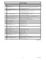
Page 49: ...49 2000225294A 14 Fault Finding 12410 Diagram 14 4 ...
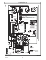
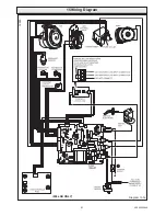
Page 51: ...51 2000225294A 15 Wiring Diagram Diagram 15 1a 12240 F28e SB ONLY ...

