59
2000225294A
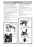
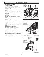
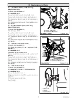
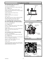
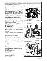
Diagram 16.17
Diagram 16.18
16 Replacement of Parts
16.21 (F24e/F28e ONLY) Three Way Valve
Refer to
sections 13.9 and 13.10.
Remove the Reduced Pressure Zone Valve Refer to
Section
16.19.
Remove the electrical connection from the three way valve,
see
diagram 16.7.
Remove the pipe assembly from between the cold water inlet
isolation valve to cold water filter housing,
see diagram 13.10.
NOTE: If there is sufficient clearance to remove the right hand
side panel and gain access to the rear union connection, it is not
neccessary to remove the pump head.
With the pump head removed as
Section 16.10.
Remove the
pipe retaining clip and disconnect the two union connections.
16.22 (F24e/F28e ONLY) Pressure Sensor
For access, refer to
section 16.1.
Refer to
section 13.9
and drain the boiler heating circuit.
NOTE: If there is sufficient clearance to remove the right hand
side panel and gain access to the rear union connection, it is not
neccessary to remove the pump head.
With the pump head removed as
Section 16.10.
Remove the
pipe retaining clip and disconnect the two union connections.
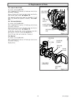
Remove the three way valve.
Refer to
diagram 16.18.
Disconnect the electrical lead by pushing up retaining tab to
withdraw the lead plug.
Remove the retaining clip to remove the low water pressure
sensor.
Fit new 'O' ring.
Fit the new pressure sensor. Refill vent and pressurise the
boiler.
Check for leaks.
16.22a (F28e SB) Pressure Sensor
For access, refer to
section 16.1.
Refer to
section 13.9
and drain the boiler heating circuit.
Refer to
diagram 16.18a.
Disconnect the electrical lead by pushing up retaining tab to
withdraw the lead plug.
Remove the retaining clip to remove the low water pressure
sensor.
Fit new 'O' ring.
Fit the new pressure sensor. Refill vent and pressurise the
boiler.
Check for leaks.
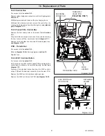
16.23 (F24e/F28e ONLY) Domestic Cold Water
Inlet Filter
For access, refer to
section 16.1.
Refer to
section 13.8.
Fit new 'O' rings.
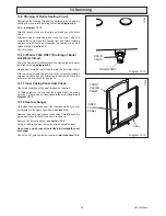
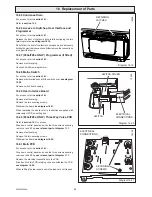
16.24 Inner Casing Panel Seal
For access, refer to
section 16.1.
Refer to
section 13.11.
ELECTRICAL
CONNECTIONS
RETAINING
CLIP
PRESSURE SENSOR
12193
THREE WAY VALVE
(F24e/F28e ONLY)
(F24e/F28e ONLY)
(F28e SB ONLY)
Diagram 16.18a
RETAINING
CLIP
PRESSURE SENSOR
12246
Summary of Contents for EnviroPlus F24e
Page 18: ...18 2000225294A Diagram 5 1 11907 5 Boiler Schematic F24e F28e ONLY ...
Page 19: ...19 2000225294A 5 Boiler Schematic Diagram 5 1a 12248 BYPASS F28e SB ONLY ...
Page 49: ...49 2000225294A 14 Fault Finding 12410 Diagram 14 4 ...
Page 51: ...51 2000225294A 15 Wiring Diagram Diagram 15 1a 12240 F28e SB ONLY ...

