48
2000225294A
14 Fault Finding
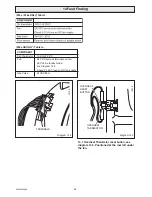
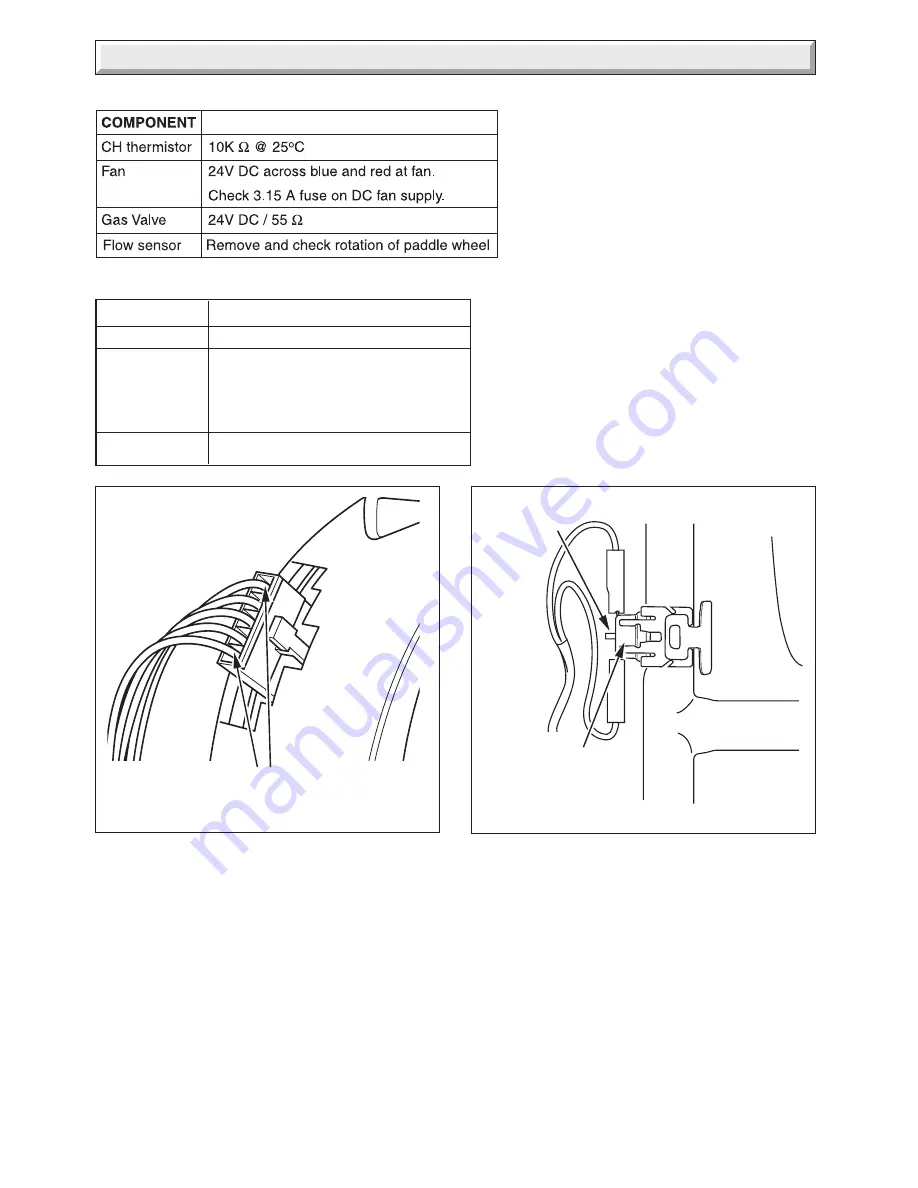
Diagram 14.2
TERMINALS
(F24e / F28e ONLY) Table 1.
12195
Diagram 14.3
OVERHEAT
THERMISTOR
12216
OVERHEAT
RESET
BUTTON
(F28e SB ONLY) Table 1a.
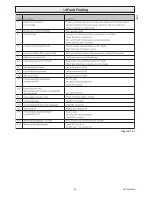
COMPONENT
C.H. thermistor
10K
Ω
@ 25
°
C
Fan
24V DC accross terminals on fan,
40V dc in standby mode,
see diagram 14.2.
Check 3.15 AT fuse on DC fan supply.
Gas Valve
24VDC/55
Ω
14.1 Overheat Thermistor reset button, see
diagram 14.3. Positioned at the rear left under
the fan.
Summary of Contents for EnviroPlus F24e
Page 18: ...18 2000225294A Diagram 5 1 11907 5 Boiler Schematic F24e F28e ONLY ...
Page 19: ...19 2000225294A 5 Boiler Schematic Diagram 5 1a 12248 BYPASS F28e SB ONLY ...
Page 49: ...49 2000225294A 14 Fault Finding 12410 Diagram 14 4 ...
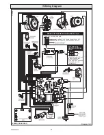
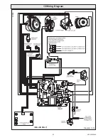
Page 51: ...51 2000225294A 15 Wiring Diagram Diagram 15 1a 12240 F28e SB ONLY ...

