25
2000225294A
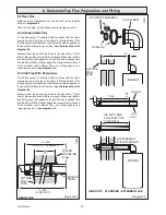
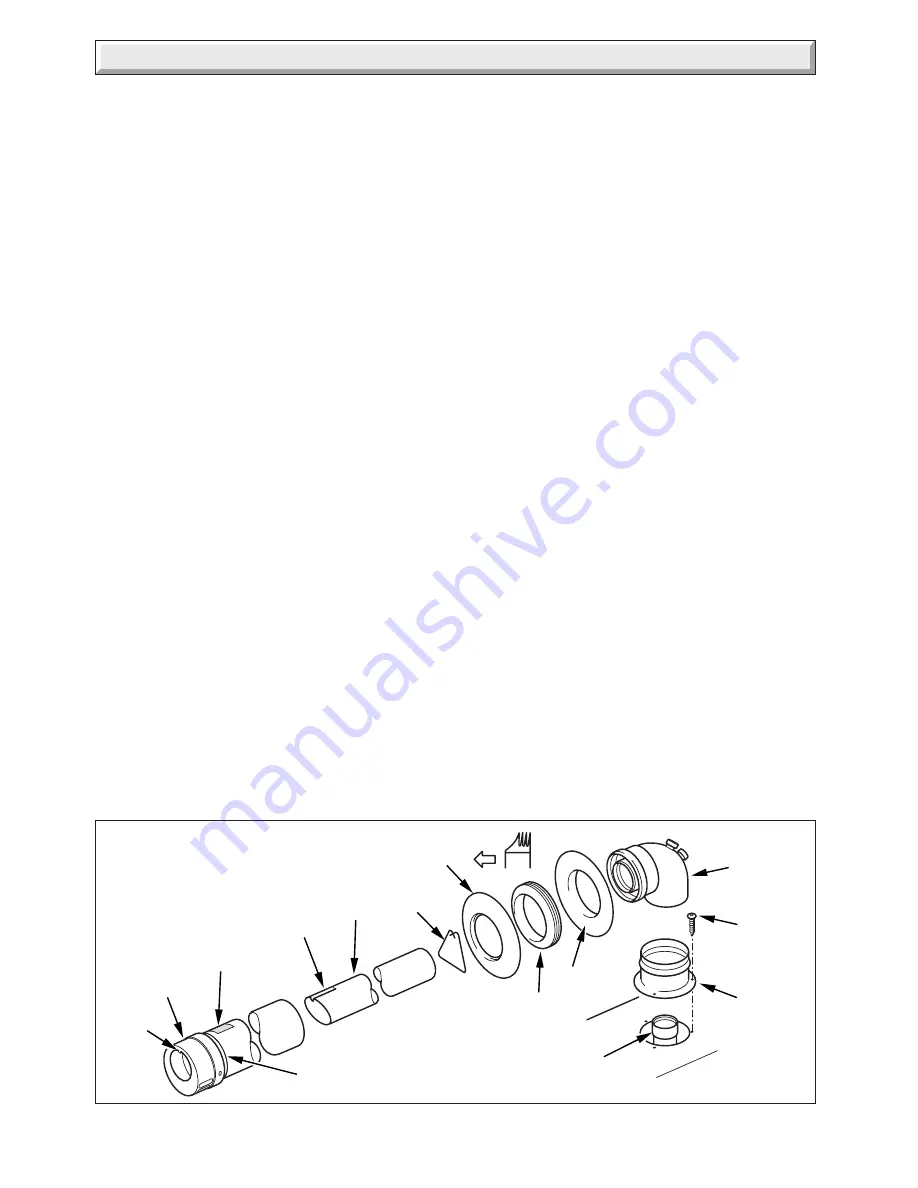
Diagram 8.6
11903
GROOVE
TAB
'A'
'B'
'G'
'H'
'D'
'E'
'F'
SCREW
(3 OFF)
'C'
'UP'
LABEL
GROOVE
FLUE PIPE
8 Horizontal Top Flue Preparation and Fitting
8.5 Flue Assembly
The flue assembly is an entirely push fit design.
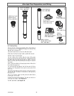
The lip seals should be fitted in the correct orientation into the
flue elbow,
see diagram 8.4.
Lubricate the lip seals prior to inserting flue pipes.
Make sure all joints are properly fitted, sealed and secured.
Remove all burrs from cut pipes.
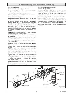
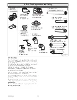
Diagram 8.5
shows the components supplied in the standard
flue kit.
Having cut the air and flue ducts as described in
sections 8.1
- 8.4
, assemble the flue as follows: the flue can be assembled
externally and internally by following sections A and C, or
entirely from inside by following sections B and C.
NOTE:
Ensure that the 'up' label on air pipe 'B' is at the top, i.e.
the tab protruding into the hole at the outer end of the pipe is
uppermost. For internal fitting it may be necessary to mark the
flue protruding internally 'top', to ensure the flue does not twist
on fitting.
A. Internal fitting
- Fit the rubber sealing collar 'D' into the
groove at the outer end of the air pipe 'B'.
Fit spacer piece 'E' over air pipe 'B', ensure correct orientation,
see diagram 8.5.
Push the air pipe 'B' through the wall until collar 'D' is clear of the
outside face of the wall.
Pull the air pipe 'B' back to ensure that collar 'D' is pulled up to
the outside wall face.
Ensure spacer piece 'E' is pushed into the wall,
see diagram
8.4.
Fit sealing flange 'F' over the air pipe but not against the inside
wall face.
B. External fitting
- Fit the rubber sealing collar 'D' into the
groove at the outer end of the air pipe 'B'.
Push the air pipe 'B' into the wall until collar 'D' is pushed up
against the outside face of the wall.
Fit sealing flange 'F' over the air pipe and against the inside wall
face.
C. Fitting Completion
- Ensure flue pipe 'A' is fully inserted into
the air pipe 'B' ensuring that the groove on the outer end
engages in the air pipe tab.
Ensure flue pipe spacer 'C' is correctly located between 'A' and
'B'.
Attach any extension pieces as necessary.
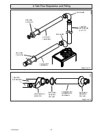
8.6 Flue Attachment to Boiler,
refer to Diagram 8.6.
Internal rear flue fitting.
While the flue spigot 'H' is attached
to the boiler, push the flue elbow 'G' into the adaptor. Pull air pipe
'B' and flue duct 'A' into the flue elbow. A small amount of
lubricant should be applied to the rubber seals in the elbow to
facilitate this.
Push rubber sealing collar 'F' along flue against inside wall face.
External and Side flue fitting.
Remove flue spigot 'H' from the
boiler and fit 'H' to the flue elbow 'G' and fit flue elbow 'G' to air
pipe 'B' and flue duct 'A'. A small amount of lubricant should be
applied to the rubber seals in the elbow to facilitate this.
Secure the flue spigot 'H' to the top of the boiler with the 3 screws
provided.
'E'
Summary of Contents for EnviroPlus F24e
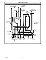
Page 18: ...18 2000225294A Diagram 5 1 11907 5 Boiler Schematic F24e F28e ONLY ...
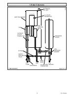
Page 19: ...19 2000225294A 5 Boiler Schematic Diagram 5 1a 12248 BYPASS F28e SB ONLY ...
Page 49: ...49 2000225294A 14 Fault Finding 12410 Diagram 14 4 ...
Page 51: ...51 2000225294A 15 Wiring Diagram Diagram 15 1a 12240 F28e SB ONLY ...


