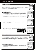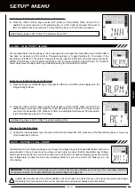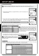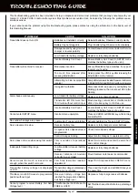
Page 50
gLOSSaRY OF TERMS
Programming Keys:
The Programming Keys are used to facilitate transmitter programming. The four Programming Keys consist
of two MENU keys (Right and Left), one +/INC (Increase) key, and one NO/- (Decrease) key.
Programming Toggle Switch:
The two Toggle Switches perform the same functions as the four Programming Keys. The Toggle
Switches make it easy to make programming changes during use. For example, to change the Steering Dual Rate percentage value
or Activate the Dig and Burn functions while your driving.
Programming Window:
The area in the Multi-Function LCD that the actual programming of the different transmitter functions
takes place.
Receiver Battery Voltage Fail Safe:
Used to set a custom voltage that the Receiver Battery Fail Safe function will Activate at.
When your receiver battery voltage drops to the programmed voltage, the throttle servo will move to the predetermined position.
If this occurs, recharge or replace your receiver batteries.
Right Menu Key:
Scrolls right (forward) through the individual functions assigned to the currently highlighted menu.
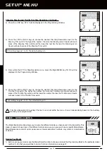
Servo Reversing:
Used to electronically switch the direction of servo travel. For example, if you move the steering control stick
to the right, and the steering servo moves to the left, you can use the Servo Reversing function to make the steering servo move
to the left. The Servo Reversing function is available for all three channels.
Servo Speed:
Used to slow down the transit speed of the steering and throttle servos. Servo transit speed can be slowed in both
the Forward and the Return to Center directions independently. When driving your model, proper steering and throttle control are
vital. For example, lowering the transmit speed of the steering servo can help to limit excessive steering, which will enable you to
achieve smoother cornering. In addition, lowering the throttle servo speed can help to ensure smooth throttle control.
Servo Sub-Trim:
Used to correct the neutral trim setting for steering and throttle, making it possible to center the trim switches
while ensuring the steering and throttle servo horns remain centered. The Sub-Trim function can also be used for Auxiliary
Channel 3 when it is being used with a Mix.
Setup Menu Icon:
Displayed on the Multi-Function LCD to indicate when the transmitter is in the SETUP menu.
Steering Dual Rate:
Used to change the amount of steering servo travel compared to the amount of physical movement of the
steering control stick. For example, by increasing the Steering Dual Rate, you can make the steering servo travel more which
might prevent your model from pushing during turns. If your model oversteers during turns, you can reduce the amount of
Steering Dual Rate.
Steering Trim Switch:
Used to adjust the center trim of the steering servo.
Steering Control Stick:
Controls the steering function of your model. The Steering Control Stick spring tension is adjustable to
suit your preference.
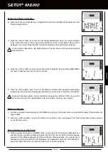
Step Auxiliary:
Used to program Auxiliary Channel 3 to move in defined Step amounts throughout its entire range of travel. Step
values can be defined, then you can move the Auxiliary Channel 3 servo in those Step amounts, using either the TRM switch, the
+/INC and DEC/- keys, or the Toggle Switches. For example, if you are running a boat that features a remotely adjustable trim
plate, you can use the Step Auxiliary function to operate the trim plate up or down. Step values are adjustable for very fine servo
travel or for large amounts of servo travel at one time.
Step Value:
A preset amount that the servo will travel when the trim switch is pressed once. The step value can be adjusted so
that the servo either moves more or moves less when the trim switch is pressed.
Suppression Capacitor:
Primarily used on electric motors, a suppression capacitor helps eliminate electrical noise that could
interfere with the operation of your radio control system.
Tandem Steering:
Used with Four Wheel Steering, the front wheels pivot opposite to the rear wheels.
Throttle Control Stick:
Controls the Throttle and Brake (if equipped) functions of your model. The Throttle Control Stick spring
tension is adjustable to suit your preference.
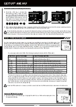
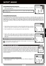
Trim Step Resolution:
Used to adjust how far the Steering and Throttle servos travel when the trim switches are pressed. You
can increase the resolution by decreasing the Trim Step Resolution value, so that the Steering and Throttle servos travel less
when you press the trim switches. This makes it possible to fine-tune the settings extremely accurately. In addition, you could
decrease the resolution by increasing the Trim Step Resolution values, so that the Steering and Throttle servos travel more when
you press the trim switches. This setting may not be as accurate, although you can set large amounts of trim faster.
Trim Switch Assign:
Used to assign several different operations to the TRM switch on top of the transmitter. This allows you
to easily control during use a specific Auxiliary function that you've assigned to the TRM switch. For example, you could assign
the Step Auxiliary function to the TRM switch and control your glow-powered model's needle valve or your boat's adjustable trim
step. In addition, you can change the Step Resolution of the TRM switch to change how far the servo travels with each press of
the TRM switch.
Throttle Trim Switch:
Used to adjust the center trim of the throttle servo.
Top Menu Icon:
Displayed on the LCD to indicate that you are at the top level of a specific SETUP menu.
Summary of Contents for Gemini X
Page 1: ...Page 1 ...
Page 55: ...Page 55 NOTES ...

