3
.
Installing the Product
English 8/2020. Rev 0.3
37
3.10.3
Battery Module Installation
1.
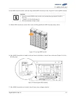
Transport battery modules to the installation location.
2.
Measure the modules’ voltage and internal impedance. All modules in one rack frame must be near the same state of charge.
The batteries must have an output within 300mV of each other and internal impedance difference of 1.3mΩ. Refer to Table
3-8: Module Voltage and Internal Impedance.
3.
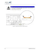
Place the battery modules on the rack frame.
Important
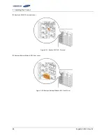
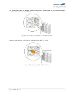
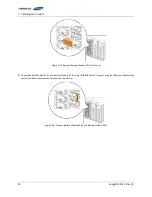
Samsung recommends installing Battery Modules in the upper shelves first and proceeding to
the bottom.
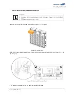
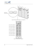
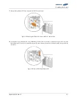
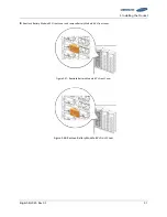
(Two Type B battery modules are inserted in the ninth shelf from the bottom.)
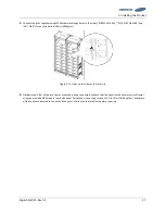
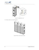
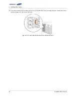
Sixteen battery modules can be inserted into a rack frame as shown in Figure 3-27.
Refer to 2.1.1 for information on the different battery module types.
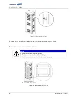
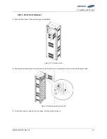
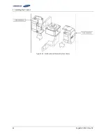
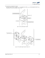
Figure 3-25: Insertion of Modules on the Ninth Shelf from the Bottom
Two Type B Battery
Modules
Summary of Contents for U6A4
Page 1: ...English 8 2020 Rev 0 3 LIB System for UPS U6A4 Installation Manual 128S ...
Page 4: ...English 8 2020 Rev 0 3 ...
Page 10: ...Important Safety Instructions vi English 8 2020 Rev 0 3 ...
Page 17: ...Table of Contents English 8 2020 Rev 0 3 vii ...
Page 18: ......
Page 125: ...Memo ...
Page 126: ...Memo ...
Page 127: ...Memo ...
Page 128: ...www SamsungSDI com ...


