


3
.
Installing the Product
English 8/2020. Rev 0.3
47
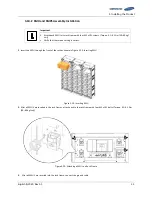
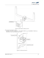
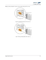
1.
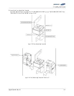
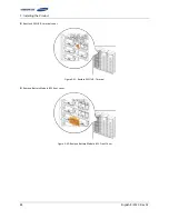
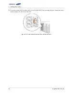
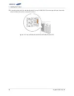
Remove Battery Module #1’s front cover and the SMU B- terminal cover.
Figure 3-39: Removing the Module #1’s Cover and SMU B- Terminal Cover
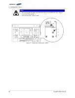
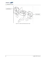
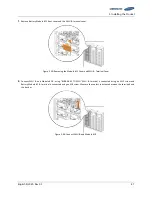
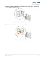
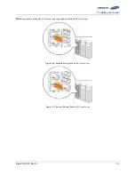
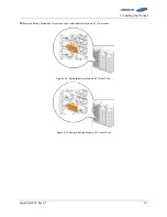
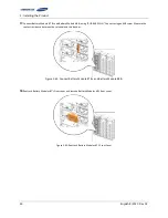
2.
Connect SMU B- and Module #1 B- using “BUSBAR M TO SMU.” SMU B- terminal is connected using an M12 screw and
Battery Module #1 B- terminal is connected using an M8 screw. Measure the contact resistance between the terminals and
the bus bar.
Figure 3-40: Connect SMU B- and Module #1 B-
Summary of Contents for U6A4
Page 1: ...English 8 2020 Rev 0 3 LIB System for UPS U6A4 Installation Manual 128S ...
Page 4: ...English 8 2020 Rev 0 3 ...
Page 10: ...Important Safety Instructions vi English 8 2020 Rev 0 3 ...
Page 17: ...Table of Contents English 8 2020 Rev 0 3 vii ...
Page 18: ......
Page 125: ...Memo ...
Page 126: ...Memo ...
Page 127: ...Memo ...
Page 128: ...www SamsungSDI com ...