


Alignment & Adjustment
Samsung Electronics
3-13
3-4-2 Conditions for Measurement
1. On the basis of toshiba ABL pattern : High Light level (57 IRE)
■
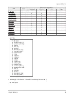
INPUT SIGNAL GENERATOR : MSPG-925LTH
* Mode NO 1 : 744X484@60 Hz
NO 6 : 1280X720@60 Hz
NO 21 : 1024X768@60 Hz
* Pattern NO 24 : B&W Lattice Pattern
NO 16 : Toshiba ABL Pattern
2. Optical measuring device : CA210 (FL)
Please use the MSPG-925 LTH generator for model HP-R5052
3-4-3 Method of Adjustment
1. Adjust the basic level of Component,PC and CVBS input signals.
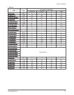
a) Enter factory Calibration, confirm the ADC data (Component, PC, AV Modes).
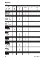
* ADC default value : Table 1
* You must perform Calibration in the Lattice pattern before adjusting the White Balance.
* If you perform Calibration in a pattern other than the Lattice pattern, it causes a malfunction and the operation will not finish.
In this case, press the "EXIT" button on the remote control to terminate the operation.
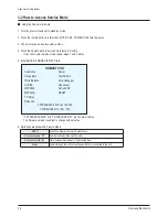
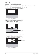
1) Enter Service mode.
2) Apply the NTSC Lattice (No 1) pattern signal to the VIDEO IN port.
3) Press the Source key to switch to "AV/S-VIDEO" mode.
4) After confirming that the Lattice pattern appears, select the "Calibration" menu.
5) Select the "AV Calibration" menu.
6) In "AV Calibration Off" status, press the "
▶
" key to perform Calibration.
7) When Calibration is complete, it returns to the high-level menu.
8) Apply the 720p Lattice (No 6) pattern signal to the COMPONENT IN (Y/Pb/Pr) port.
9) Press the Source key to switch to "COMPONENT" mode.
10) After confirming that the Lattice pattern appears, select the "Calibration" menu.
11) Select the "COMP Calibration" menu.
12) In "COMP Calibration Off" status, press the "
▶
" key to perform Calibration.
13) When Calibration is complete, it returns to the high-level menu.
14) Apply the 1024x768 Lattice (No 21) pattern signal to the PC IN port.
15) Press the Source key to switch to "PC" mode.
16) After confirming that the Lattice pattern appears, select the "Calibration" menu.
17) Select the "PC Calibration" menu.
18) In "PC Calibration Off" status, press the "
▶
" key to perform Calibration.
19) When Calibration is complete, it returns to the high-level menu.
20) All Calibration operations are complete.
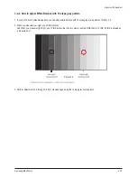
Picture 2-1 B&W Lattice Pattern
Summary of Contents for HP-R5052
Page 14: ...1 6 Samsung Electronics MEMO ...
Page 40: ...3 20 Samsung Electronics MEMO ...
Page 43: ...Samsung Electronics 5 2 MEMO ...
Page 51: ...6 8 Samsung Electronics MEMO ...
Page 59: ...8 4 Samsung Electronics MEMO ...
Page 61: ...9 2 Samsung Electronics MEMO ...
Page 84: ...11 12 Samsung Electronics MEMO ...
Page 92: ...12 8 Samsung Electronics MEMO ...
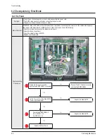
Page 112: ...Circuit Description 13 20 Samsung Electronics Drive Board Connector Layout 1 X Main ...
Page 122: ...13 30 Samsung Electronics MEMO ...


