18
Tel: 886.909 602 109 Email: [email protected]
color contrast corresponding to different testing environment such as outdoor, nighttime, and normal testing environment.
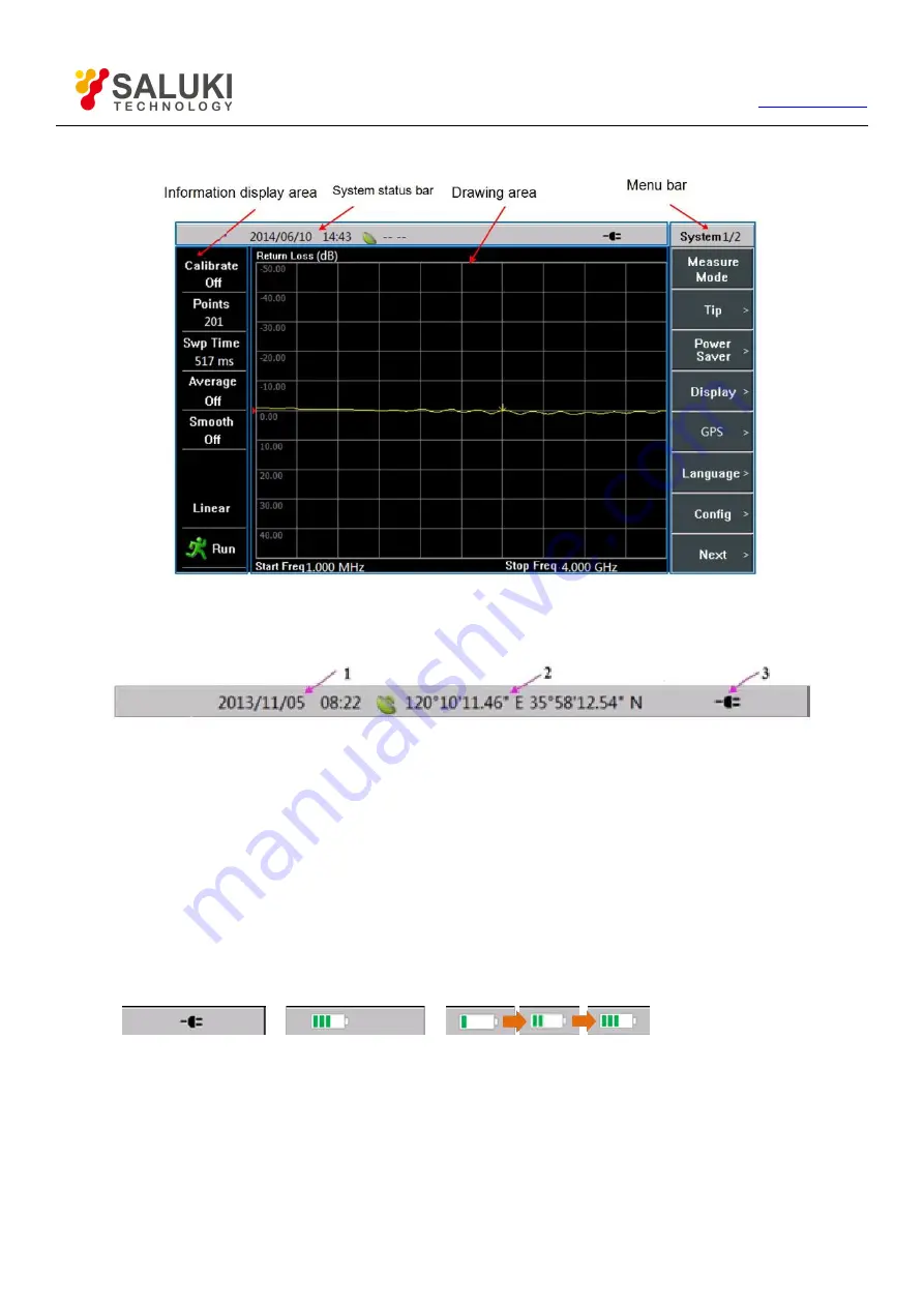
Figure 3-11 Touch Screen Display Area
3.3.1.
System Status Bar
Figure 3-12 System Status Bar
1) Analyzer system date and time: Operators can set or change through
【
System/Local
】
→[SET]→[Date/Time].
2) GPS display area: Operators can connect the GPS antenna and then turn on GPS through
【
System/Local
】
→[GPS]→[GPS On
Off]. GPS information will be displayed in this area.
3) Power supply identification area: This area includes the following three display status, as shown in Figure 3-13:
a) when the battery is not installed, it displays the external power supply pattern;
b) when the battery is installed and external power supply is not connected, it displays the current status of electric quantity;
c) when the battery is installed and external power supply is connected, it displays the charging status.
a) External power supply
b) Display of electric quantity
c) Charging status
Figure 3-13 Power Supply Identification
3.3.2.
Information Display Area


