background image

68

Tel: 886.909 602 109 Email: [email protected]

www.salukitec.com

Figure 10-2 IP Address Dialog Box

After the communication interface has been selected, click

Connect

as shown in Figure 10-1. If this key becomes into

Discon

, it

means that the instrument has been successfully connected, as shown in Figure 10-3.
After the communication interface has been selected, click

Connect

as shown in Figure 10-1. If this key becomes into

Discon

, it

means that the instrument has been successfully connected, as shown in Figure 10-3.

Figure 10-3 Change of the Key after Successful Connection

10.2.2.

Trace Collection & Storage

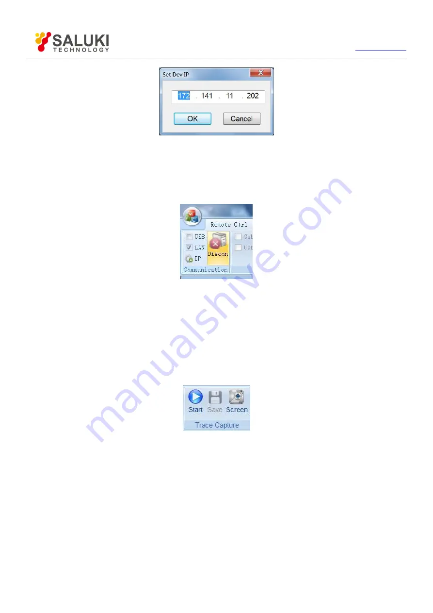
Trace collection refers to gather the test curves of S3101 in real time, which are then displayed in window of the software toolkit. Click the

Remote Ctrl

tab, and then select the

Start

key in the

Trace Capture

group to start to collect traces, as

shown in Figure 10-4. Software will display the trace collection window with title of “Trace Capture”, and then the

Start

key become into

Stop

, as shown in Figure 10-5.

Figure 10-4

TRACE COLLECTION

Group

Summary of Contents for S3101 Series

Page 1: ...S3101 Cable Antenna Analyzer User Manual Saluki Technology Inc...

Page 2: ...nd User Manual 1 PC 8 Certificate of Calibration 1 PC Options of the S3101 cable antenna analyzer Option No Item S3101 01 USB Power Measurement Software S3101 02 Backup Rechargeable Li ion Battery S31...

Page 3: ...Tel 886 909 602 109 Email sales salukitec com www salukitec com 3 Option No Item S3101 15 Low Loss Test Cable N JJ 80cm S3101 16 Functional Soft Case S3101 18 Hard Case Carrying Case...

Page 4: ...product meets the indicator requirements of the manual at the time of delivery Calibration and measurement are completed by the measuring organization with qualifications specified by the state and re...

Page 5: ...886 909 602 109 Email sales salukitec com www salukitec com 5 Contacts Service Tel 886 909 602 109 Website www salukitec com Email sales salukitec com Address No 367 Fuxing N Road Taipei 105 Taiwan R...

Page 6: ...3 2 Top Panel Overview 16 3 2 1 Power Interface 16 3 2 2 Digital Interface 17 3 2 3 Test Port 17 3 3 Screen Area Overview 17 3 3 1 System Status Bar 18 3 3 2 Information Display Area 18 3 3 3 Trace d...

Page 7: ...ker mode 35 5 7 5 Basic marker operation 35 5 7 6 Quick marker operation 36 5 7 7 Switch of marker position under list sweep 36 5 8 Display 37 5 8 1 Open dual window 37 5 8 2 Activate window 37 5 8 3...

Page 8: ...Management 54 9 1 Introduction 54 9 2 Measurement Mode 54 9 3 TIP 55 9 4 Power Saving Mode 56 9 5 Display 57 9 6 GPS Function 59 9 7 Setup 60 9 7 1 Date Time 60 9 7 2 LAN 60 9 7 3 Touch Screen Calibr...

Page 9: ...9 Tel 886 909 602 109 Email sales salukitec com www salukitec com 10 2 6 File Transfer 74 10 2 7 Check the Software Version 75 10 2 8 Drawing Printing 75 10 2 9 Generate the Test Report 76...

Page 10: ...ncy in the field 1 1 Key Feature Frequency range 1MHz to 4GHz 8GHz Multiple measurement functions Return Loss VSWR Cable Loss DTF Return Loss DTF VSWR Smith Chart and Port Phase Impact dust and splash...

Page 11: ...omply with these instructions accordingly 2 1 Device safety a Use designated packing container in shipping and avoid falling or violent collisions in moving which may cause damages to the device b Use...

Page 12: ...ectric shock Use dry or moist soft cloth to clean the device Do not clean the internal of the device d Before using this device personnel need to be trained When using the device concentration is requ...

Page 13: ...iled introduction to the front panel of S3101 You can get generally familiar with the basic application of the panel keyboard of the instrument by reading it The front panel of S3101 Cable Antenna Ana...

Page 14: ...ibration status ON OFF and selection of calibration kit model Save Recall Used to realize the file operations including save and load measurement status and measurement trace screen capture storage po...

Page 15: ...correspondence relationship between entered character and press times is as shown below in Table 3 1 Table 3 1 Instruction to Keys on the Keyboard Press Times Figure Key 1 2 3 4 1 1 A B C 2 2 D E F 3...

Page 16: ...ter of the knob shaped like umbrella Therefore do not try to hold down on side with a single finger to rotate the knob when using which will increase the friction between the knob and shell Operators...

Page 17: ...ect external USB instrument such as USB storage device USB mouse and USB keyboard 3 2 3 Test Port Figure 3 10 Test Port 1 GPS antenna used to connect GPS antenna instrument and support positioning of...

Page 18: ...through System Local GPS GPS On Off GPS information will be displayed in this area 3 Power supply identification area This area includes the following three display status as shown in Figure 3 13 a wh...

Page 19: ...esponding to the points then the label information set of those point will be displayed in the drawing area in the middle of the display screen and the trace sweep points can be reset via numeric keys...

Page 20: ...n the user can click the menu to select the corresponding menu items and sett measurement parameters The menu bar corresponding to the Meas is as shown in Figure 3 16 Figure 3 16 MEAS Menu Bar 3 4 Bat...

Page 21: ...Charging a Battery User can recharge the battery in the S3101 Cable Antenna Analyzer while the analyzer is operating or when it is turned off The charging procedures are as follows 1 Install the batte...

Page 22: ...then the instrument enters the main program initialization interface and displays Initializing please wait After the main program starts it will show an internal self test report and the user can obse...

Page 23: ...y click Cal Kit menu to select the calibration kit model and then click Enter 2 Click M Cal and the calibration wizard will prompt saying Please connect OPEN and start calibrating by pressing correspo...

Page 24: ...ompt LOAD Measuring After completing the load measurement the Load item on the right side of the menu bar is underlined as Load and the prompt massage saying Please Press Done soft key to finish the c...

Page 25: ...le the configuration of embedded electronic calibration of the test does not affect the use and performance of mechanical calibration kits They can be used to meets the testing requirements of a varie...

Page 26: ...5 Start to Perform Embedded Calibration 3 After completing calibration the display interface shows the prompt saying Finish embedded calibration and the calibration status automatically displays from...

Page 27: ...d then select the appropriate frequency unit to complete the start frequency setting Figure 5 1 Input Start Frequency 3 Click the touch screen Stop Frequency menu to input the appropriate stop frequen...

Page 28: ...h screen Top menu to input the appropriate top amplitude value by turning the knob or or numeric keys and then press Enter key to complete inputting the value Figure 5 3 Input Top Amplitude Value 3 Cl...

Page 29: ...s of auxiliary parameters of the current test including sweep time sweep points average smooth and IF bandwidth 5 4 1 Set trigger mode 1 Press Sweep Setup key to enter Sweep Setup menu bar 2 Press the...

Page 30: ...Antenna Analyzer provides two modes automatic and manual modes In automatic mode the Analyzer calculates the minimum time required for sweeping one screen based on the current state of the instrument...

Page 31: ...lts and reducing trace noise The noise floor can reduce by 10dB with each reduce of 10 times of IF bandwidth S3101 Cable Antenna Analyzer supports variable bandwidth IF filter wherein the frequency ba...

Page 32: ...isplayed through the average of adjacent data points and the ratio of adjacent data points to be averaged and total points is called smooth aperture S3101 Cable Antenna Analyzer sets the smooth apertu...

Page 33: ...ws 1 Press Limit key to enter limit menu bar 2 Click the touch screen Mode Up Low menu to select the type of edited limit line upper or lower limit line 3 Click the touch screen Edit menu to enter Lim...

Page 34: ...ave menu to input the file name in the popped out box and then press Enter key to complete limit line store Press Limit key to enter the limit menu bar Then click the touch screen Recall menu to selec...

Page 35: ...ween the two markers range or quickly set M1 to peak and M2 to valley as shown in below figure Figure 5 13 Peak Valley Search 5 7 4 Marker mode The Analyzer provides two marker modes Standard Mode and...

Page 36: ...M1 executes peak search and M2 executes valley search 5 Click M1 To Boundary menu then M1 executes search to the last sweep point of trace and press M1 To Boundary again then M1 executes search to the...

Page 37: ...he active window 1 Press Meas to enter the measurement menu bar 2 Click the appropriate menu in the menu bar to select the appropriate measurement data format to change the measurement format of the c...

Page 38: ...orming any type of trace operation it must store a reference trace in memory which can be obtained through recall of trace file and as which the current trace is set 5 9 1 1 Save current trace as refe...

Page 39: ...n 5 9 3 Trace Display Each window can display up to two traces and if a reference trace has been obtained the traces can be displayed through the following steps 1 Press Trace to enter Trace menu bar...

Page 40: ...d cable system Cable Loss Cable loss is used to test the consistency or loss of energy on the transmission cable Cable loss measurement is a method derived from return loss measurement Fault Location...

Page 41: ...propriate calibration kit to complete the calibration 4 Connect the Analyzer to the DUT of which the terminal is antenna in cable loss measurement DUT shall connect the short circuit 5 Press Ampt key...

Page 42: ...ency and then the distance range to be measured that is start distance and stop distance and also select the model of cable measured or input the cable velocity factor and cable loss 3 Press Cal key t...

Page 43: ...tenna tester uses cable antenna test mode in default You may switch to Power Measurement mode following the steps below 1 Press System Local key and enter system menu bar 2 Click Measure Mode menu and...

Page 44: ...nformation setting of maximum scale will be displayed in Main display area The information can be reset with knobs keys or numeric keys as shown in Figure 10 2 Figure 10 2 Information Display Area Mai...

Page 45: ...parts menu bar title and menu items Click function keys on front panel of Analyzer then menu bar of corresponding title will be spread in the right side of touch screen You may select menu items and...

Page 46: ...sured power will be obtained which will lead to more accurate measured values Offset function When power of source under test is beyond measurement range it is required to attenuate or enlarge signal...

Page 47: ...cale menu only based on requirements application programs will automatically adjust the maximum value and the minimum value of dial in accordance with power data measured The operation is as below 1 P...

Page 48: ...ales salukitec com www salukitec com 3 Click Zero menu the screen will indicate Calibration Finish calibration in a few seconds to indicate zero calibration is completed As shown in Figure 10 7 Figure...

Page 49: ...data or storing data in specific format for the convenience of analyzing and processing in externally controlled software Storage medium is internal memory in default state Instrument setting and meas...

Page 50: ...recall previous status stored Status recalling steps are as follows 1 Press Save Recall 2 Click Recall State menu to bring up a status list of storage while menu bar enters Recall menu bar as shown in...

Page 51: ...r key to complete storage of trace As shown in the following picture Figure 8 4 Trace Storage You may also recall previous stored status as status recalling Trace recalling steps are as follows 1 Pres...

Page 52: ...r some circumstances more directly or use image data while drafting documents in the future as Analyzer provides Screen Capture function You may get an easy access to obtain data results of current te...

Page 53: ...the right side of dialog box and press keys or use knobs to select destination path or directly click file paths where copied documents or folders located on the right side of touch screen 5 Click Sta...

Page 54: ...apter 10 are used to perform distance control over Analyzer A Remote control notice is called up next to power notice while Analyzer does not respond to keyboard keys any more You may press System Loc...

Page 55: ...ring up a dialog box of Please enter a label Input label content in the dialog box and click Confirm key on dialog box or press Enter key to complete label setting You may also click Edit Tip menu dir...

Page 56: ...obs and numeric keys Press Enter key and complete sleep time setting 30s before system enters sleep mode a Notice dialog box will be brought up and indicate system will enter sleep mode soon as shown...

Page 57: ...ing environment Setting steps of instrument display mode are as follows 1 Press SYSTEM LOACL key and enter system menu bar 2 Click Display menu and enter menu bar 3 Click display mode on corresponding...

Page 58: ...are as follows 1 Press System Local key and enter system menu bar 2 Click Display menu and enter display menu bar 3 Click Brightness Adjustment Auto Man menu a Menu displayed as Brightness Auto Man i...

Page 59: ...nd time etc Detailed operating steps of GPS function are as follows 1 Connect GPS antenna and Analyzer 2 Press System Local key and enter system menu bar 3 Click GPS menu and enter GPS menu bar 4 Clic...

Page 60: ...11 Date and Time Setting In addition you may also switch display method of date by clicking Date Format menu in Date and Time menu bar 9 7 2 LAN Similar to common PC system you may need to reconfigur...

Page 61: ...and switch cursor to subnet mask configuration column Set subnet mask of instrument with numeric keys as shown in the following figure Figure 9 13 LAN Subnet Mask 6 Click Gateway menu on menu bar and...

Page 62: ...elow 1 Calibration with mouse connect mouse to USB A type interface of digital interface and perform Touch Screen Calibration following the steps below a Press System Local key and enter system menu b...

Page 63: ...an upgrade package you may place it under root directory of external USB memory or SD card or insert it into external memory thumb drive etc Click Software Update menu Applications software will autom...

Page 64: ...power supplying condition etc As shown in Figure 6 17 Figure 9 17 Self test of Instrument 9 9 Frequency Reference 10MHz S3101 Cable Antenna Analyzer provides input output interface for 10MHz reference...

Page 65: ...asurement guide function This function is not applicable under power meter measurement mode for faster and more convenient master of basic operation of several measurement format You may get the knowl...

Page 66: ...66 Tel 886 909 602 109 Email sales salukitec com www salukitec com Figure 9 19 Measurement Guide...

Page 67: ...ison and operation Set the parameters such as frequency sweeping points measuring format DTF parameters etc Requirements on system configuration of the computer Processor of Inter Pentium 4 or higher...

Page 68: ...Discon it means that the instrument has been successfully connected as shown in Figure 10 3 Figure 10 3 Change of the Key after Successful Connection 10 2 2 Trace Collection Storage Trace collection r...

Page 69: ...rameters Parameters which can be set include sweep frequency points average smooth set measuring format DTF parameters etc Click the Remote Ctrl tab the parameter setting area contains Frequency Point...

Page 70: ...group to pop up the dialog box of Calibrate Operating procedures of remote calibration are shown as follows 1 In the Set Cal Kit column of the dialog box click the corresponding key to select model o...

Page 71: ...ng Trace Math and Marker as shown in Figure 10 11 Figure 10 11 Trace Analysis Tab 1 Read the trace Click the Read key to pop up the drop down menu which includes Local Trace File and Dev Trace File as...

Page 72: ...e File 2 Set the Ruler Ruler of trace window can be set in the Scale group which include reference position reference value and scale You can also click Auto Scale then software will automatically adj...

Page 73: ...ied out between two traces When using this function it needs to open two trace files and then drag your mouse in a trace window to another one in order to make two traces stay within the same window a...

Page 74: ...and opening and closing the marker two keys in the middle are used for setting the current marker at extreme value as for the right Marker Set click it to edit the marker position or conduct the loca...

Page 75: ...k key in the upper right corner of the software to check its version and copyright information as shown in Figure 10 22 Figure 10 22 Key of About 10 2 8 Drawing Printing Software toolkit provides the...

Page 76: ...common items besides the drawing of current trace window Click the Recent List key in the upper left corner of software to select the Report Setting and Report Generation in the drop down list as show...

Reviews: