Communication Protocol
109
-
144
Baud rate (BPS)
Max. transmission
distance (m)
Baud rate (BPS)
Max. transmission
distance (m)
2400 1800 9600 800
4800 1200 19200 600
It is recommended to use shielded cables and make the shield layer as the grounding wires during RS485
remote communication.
In the cases with less devices and shorter distance, it is recommended to use 120
Ω
terminal resistor as the performance
will be weakened if the distance increase even though the network can perform well without load resistor.
9.3.2 RTU mode
9.3.2.1 RTU communication frame format
If the controller is set to communicate by RTU mode in MODBUS network every 8bit byte in the message includes
two 4Bit hex characters. Compared with ACSII mode, this mode can send more data at the same baud rate.
Code system
·
1 start bit
·
7 or 8 digital bit, the minimum valid bit can be sent firstly. Every 8 bit frame includes two hex characters
(0...9, A...F)
·
1 even/odd check bit . If there is no checkout, the even/odd check bit is inexistent.
·
1 end bit (with checkout), 2 Bit(no checkout)
Error detection field
·
CRC
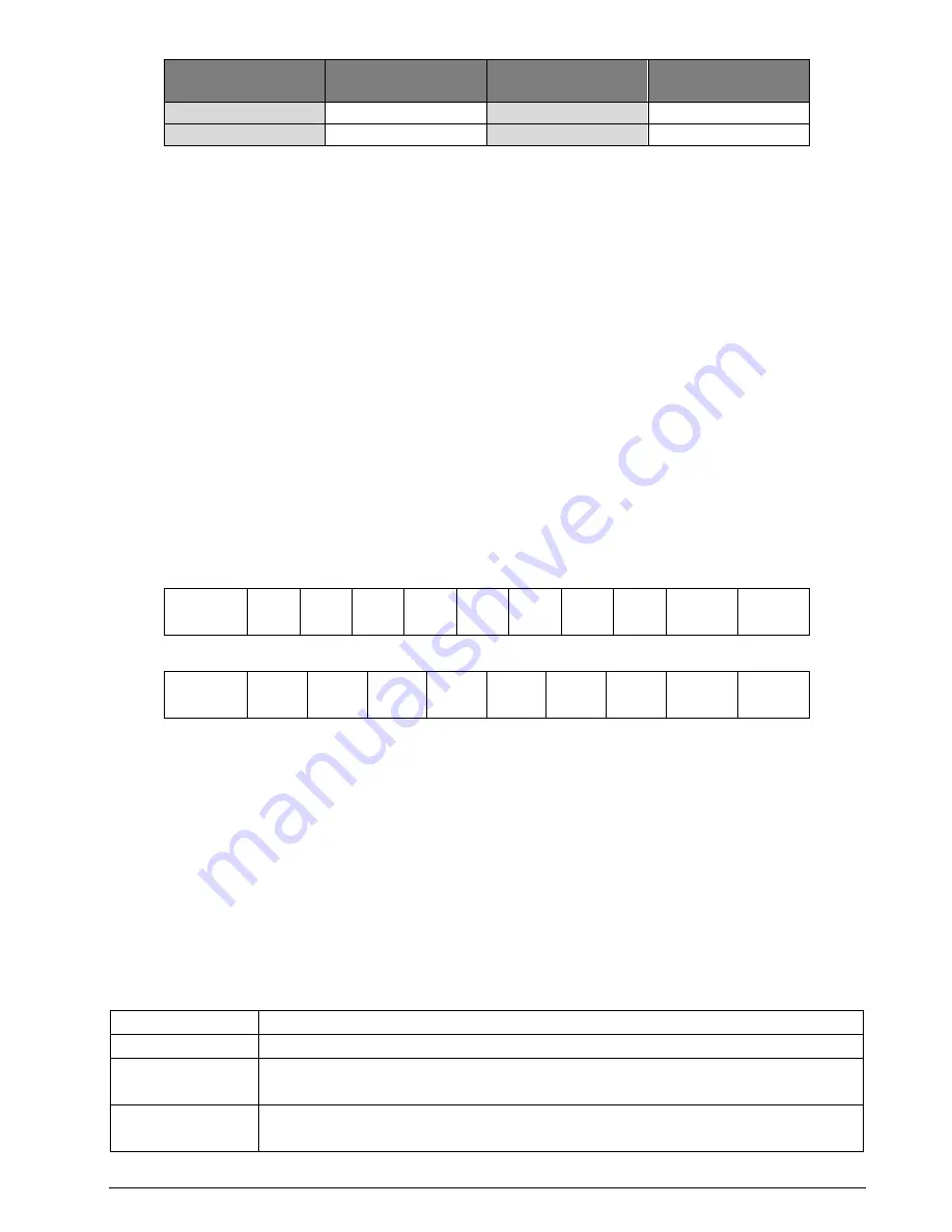
The data format is illustrated as below:
11-bit character frame (BIT1~BIT8 are the digital bits)
Start
bit BIT1 BIT2 BIT3 BIT4 BIT5 BIT6 BIT7 BIT8
Check
bit
End bit
10-bit character frame (BIT1~BIT7 are the digital bits)
Start
bit BIT1 BIT2 BIT3 BIT4 BIT5 BIT6 BIT7
Check
bit
End bit
In one character frame, the digital bit takes effect. The start bit, check bit and end bit is used to send the digital bit
right to the other device. The digital bit, even/odd checkout and end bit should be set as the same in real application.
The MODBUS minimum idle time between frames should be no less than 3.5 bytes. The network device is detecting,
even during the interval time, the network bus. When the first field (the address field) is received, the corresponding
device decodes next transmitting character. When the interval time is at least 3.5 byte, the message ends.
The whole message frame in RTU mode is a continuous transmitting flow. If there is an interval time (more
than 1.5 bytes) before the completion of the frame, the receiving device will renew the uncompleted message
and suppose the next byte as the address field of the new message. As such, if the new message follows the
previous one within the interval time of 3.5 bytes, the receiving device will deal with it as the same with the
previous message. If these two phenomena all happen during the transmission, the CRC will generate a fault
message to respond to the sending devices.
The standard structure of RTU frame:
START
T1-T2-T3-T4 (transmission time of 3.5 bytes)
ADDR
Communication address: 0~247(decimal system)(0 is the broadcast address)
CMD
03H: read slave parameters
06H: write slave parameters
DATA (N-1)
…
The data of 2*N bytes are the main content of the communication as well as the core of
data exchanging
Summary of Contents for CV50-008-4F
Page 1: ...USER MANUAL INVERTER CONTROLVIT CV50 ...
Page 2: ......
Page 84: ...84 144 Function Parameters ...
Page 101: ...Fault Tracking 101 144 8 6 4 Undervoltage fault 8 6 5 Abnormal motor heat ...
Page 142: ... ...
Page 143: ... ...


