


Automatic Backflush Filter F450
State:
05.02.2016
– 1.3
Georg Schünemann GmbH, Bremen
9-2
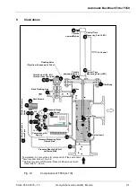
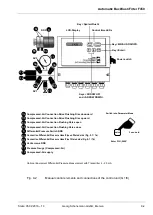
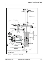
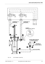
Fig. 9-2
Manual control elements and connections of the control unit (G 1/8)
SV2
3a
6a
13a
13b
SV1
3b
6b
Optional Equipment Differential Pressure Measurement with Transmitter 4
– 20 mA
Key <Spülen/Flush>
Key <EIN/AUS ON/OFF>
Key <Enter>
EIN/AUS
ON/OFF
Spülen
Flush
Enter
DDS
LCD-Display
Control time LEDs
Power switch
Keys <ARROW UP>
and <ARROW DOWN>
Switch into Parameter Mode
Enter PIN „0000“
3 sec. hold
Tasten <PFEIL RAUF>
Compressed-Air Connection Drive Flushing Disc downward
Compressed-Air Connection Drive Flushing Disc upward
Compressed-Air Connection Flushing Valve open
Compressed-Air Connection Flushing Valve close
Differential Pressure Switch DDS
Connection Differential Pressure Hose/Pipe unfiltered side (Fig. 9-1 / 7a)
Connection Differential Pressure Hose/Pipe filtered side (Fig. 9-1 / 7b)
Vent screws DDS
Pressure Gauge (Compressed-Air)
Compressed-Air supply
3a
3b
6a
6b
8
8a
8b
8c
11
14
8a
8b
8c
8
11
14
ENTER