


Automatic Backflush Filter F450
State:
05.02.2016
– 1.3
Georg Schünemann GmbH, Bremen
4-4
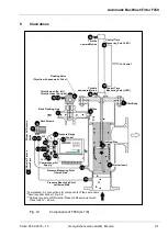
3.
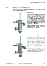
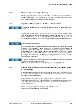
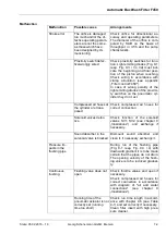
Mount the control mechanism and differ-
ential pressure switch on a wall in the
visual range of the filter, if they are not
mounted directly on the filter. The differ-
ential pressure switch should be mount-
ed horizontally with the water pressure
connections downwards and with the two
aeration nipples upwards according the
information to the left. Before setting to
work the differential pressure switch has
to be vented correct by the vent screws.
In case of ATEX-specification the de-
aeration of the measurement pipes takes
place by two separate valves, connected
upstream of the differential pressure
switch.
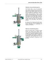
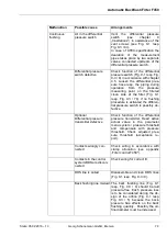
4.
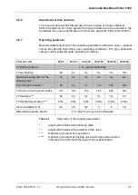
The pressure gauge mounted at the so-
lenoid valve battery should be mounted
so that the pressure balance hole shows
upwards. This has to be opened before
beginning of operation, therefore the ex-
isting aeration nippel has to be cut.
5.
If the cover is delivered separately of the filter, connect the air lines for the
pneumatic cylinder in accordance with the attached connection diagram
(see chapter 9
“Illustrations“). Connect the compressed air feed to the
compressed air station with an air connection of at least 10/1 mm. The air
pressure has to be about 87 psi (6 kg/cm
2
g) and a maximum of 116 psi (8
kg/cm
2
g) / special 50.7 psi (3.5 kg/cm
2
g).
6.
If the pneumatic control is not mounted on the filter, connect the water
hose for the differential pressure switch to the connections A and B in ac-
cordance with the connection diagram. In this process, it is important to
know that the filter’s automatic mechanism does not function if the con-
nections are changed.
7.
Connect the external signal for error. If necessary connect further signal
(OPERATION, FLUSHING, DDS HIGH, FLUSHING WITH SUPPLY) or
the inputs (FLUSHING BLOCKED, INTERLOCKED, FLUSHING ACTIVA-
TION) resp. connect the serial interface for an external controlling.
8.
If the filter has mounted a terminal box, the connection to voltage supply
as well as the external components such as flushing valve etc. is made by
screw-type terminals in the separately accessible terminal box. The fuses
are also placed here.
9.
The voltage supply has to be made as a fixed installation.
Function failure by wrong handling
Guarantee that the automatic backflush filter F450 is not supplied with pressure,
as long as the filter is switched off and/or the OPERATION contact is opened, in
order to avoid damages of the strainer insert.
TOP
Nippel (Pressure balance hole)
Vent screws
TOP
Water connections
B
A