


Automatic Backflush Filter F450
State:
05.02.2016
– 1.3
Georg Schünemann GmbH, Bremen
7-3
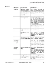
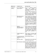
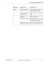
Malfunction
Possible cause
Arrangements
Continuous
flushing
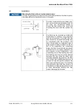
Air in the differential
pressure switch
Vent the differential pressure
switch
(see
chapter
„Illustrations“) in assistance of the
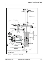
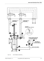
vent screws (see Fig. 9-1 resp.
Fig. 9-3 / 8c).
In case of ATEX-specification the
dearation of the measurement
pipes takes place by two separate
valves, connected upstream of the
differential pressure switch.
Differential pressure
switch defective
Check function of the differential
pressure switch (Fig. 9-1 resp. Fig.
9-3 / 8) in accordance with chapter
4.5. Loosen the differential pres-
sure hose resp. the piping during
operation
from
the
pressure
measuring point on the filtered
clean side of the filter (Fig. 9-1
resp. Fig. 9-3 / 7b). If no flushing
procedure is activated the differen-
tial pressure switch is possibly de-
fective.
Optional
Differential pressure
transmitter defective
Check function of the differential
pressure transmitter. Read active
actual value in the parameter
menu system / pressure threshold
and compensate with pressure
threshold. Check adjusted pres-
sure threshold (acceptance re-
port).
Contacts wrongly con-
nected
Check wiring in accordance with
clamp allocation (see appendix
„Filter control F450").
Contacts in the control
system/DDS are discon-
nected
Check wiring for correct fit.
DDS line is soiled
Disassemble and clean DDS lines
(Fig. 9-1 resp. Fig. 9-3 / 9).
Back flushing line mislaid The back flushing line (Fig. 9-1
resp. Fig. 9-3 / 4) should be laid
pressure-free. Each pressure loss
is to be considered during the de-
sign of the orifice (Fig. 9-1 resp.
Fig. 9-3 / 5) because the back-
pressure has effects on the back
flushing quantity. Possibly the ori-
fice diameter must be increased.