


Automatic Backflush Filter F450
State:
05.02.2016
– 1.3
Georg Schünemann GmbH, Bremen
9-1
9
Illustrations
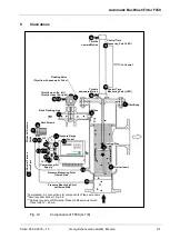
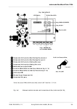
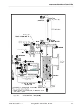
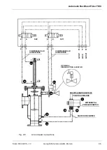
Fig. 9-1
Components of F450 (G 1/8)
SV2
SV1
*Compressed- Air connections for components of the same name
**Accuracy description in Fig. 9-2
***Optional equipment Differential Pressure Measurement with
Transmitter 4
– 20 mA
*
*
A
c
c
u
r
a
c
Orifice
Control
D
if
fe
re
n
ti
a
l
Pr
e
s
s
u
re
H
o
s
e
s
/Pi
p
e
s
Flushing Disc
Pressure Gauge
Back Flushing Line
Vent Screws
D
if
fe
re
n
ti
a
l
Pr
e
s
s
u
re
S
w
it
c
h
Compressed-Air
Supply **
Pressure Measuring Point
filtered Side
Pressure Measuring Point
unfiltered Side
Strainer Insert
Filter Body
to Control
Control Time
Measuring Point (LED)
Control Time
Measuring Point (LED)
Throttle
upward Motion
Throttle
downward Motion
Flushing Valve
(Throttle with pneumatic Drive)
upward Motion
Throttle open (6a, left)
Throttle close (6b, right)
3a
8c
8a
11
6a
8c
6b
8c
3b
8c
8b
8c
1
5
6
4
8
14
10
3b
6b
6a
3c
3a
3d
13
7a
7b
8c
9
2
3
11