background image

Adjusting Color Balance

62

Runco WindowWall Installation Guide

1

Turn on all the displays in the array and let them warm up for at least five 
minutes. The backlights must be thoroughly warm before you color balance.

2

Press 

MISC

 twice on the remote to open the 

BACKLIGHT


CONTROL


menu. Confirm 

that the 

BACKLIGHT


INTENSITY

 is greater than 1. 

3

Open the 

COLOR


BALANCE

 menu by pressing 

BALANCE

 on the remote.

Note: 

The color balance menu is a local menu. For more information about navigating local 

menus, see "Local Menus" on page 54.

4

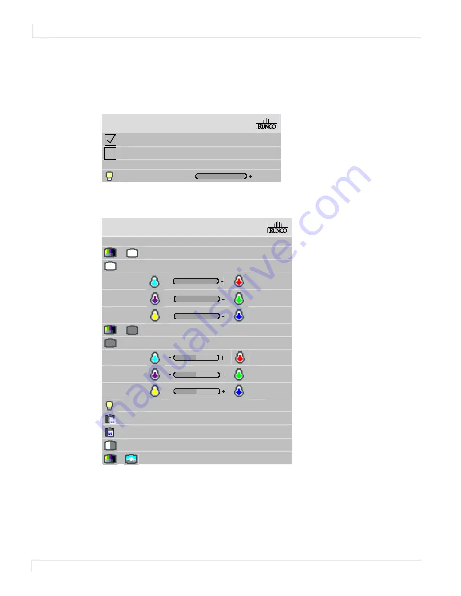
Press the ** button to show the menu on all displays.

B a c k l i g h t   C o n t r o l

A u t o   B a c k l i g h t   o n

Tu r n   B a c k l i g h t   O f f   W h e n   N o   S o u r c e   ( D P M S )

D P M S   D e l a y

1   h r

B a c k l i g h t   I n t e n s i t y

1 0

C o l o r   B a l a n c e  

C o l o r   Te m p e r a t u r e

N a t i v e

W h i t e   Te s t   P a t t e r n

W h i t e   B a l a n c e   -   A l l

( C l i p b o a r d )

R e d

1 0 0

( 1 0 0 )

G r e e n

1 0 0

( 1 0 0 )

B l u e

1 0 0

( 1 0 0 )

G r a y   Te s t   P a t t e r n

G r a y  B a l a n c e   -   A l l

R e d

7

( 7 )

G r e e n

7

( 7 )

B l u e

7

( 7 )

B a c k l i g h t   A d j u s t m e n t

+ 0

C o p y   t o   C l i p b o a r d

R e c a l l   F r o m   C l i p b o a r d

R e s e t   t o   D e f a u l ts

R e m o v e   Te s t   P a t t e r n

Summary of Contents for WindowWall

Page 1: ...Runco WindowWall Installation Guide...

Page 2: ......

Page 3: ...any years of unparalleled video performance This RuncoCare Standard Limited Warranty is provided free of charge by Runco International LLC Runco with the purchase of a covered Runco product The follow...

Page 4: ...This warranty is not transferable You may be required to provide proof of purchase in order to receive warranty services RuncoCare Standard Claim Procedure In the event of a product defect please fol...

Page 5: ...xclusions This RuncoCare Standard Limited Warranty does not include or is limited by the following 1 Products not purchased from an authorized Runco dealer 2 Rental costs incurred by the customer in t...

Page 6: ...viewing distance The following are Runco s criteria for identifying bright or dark sub pixels that would be considered unacceptable a the number of bright or dark sub pixels b the location of the bri...

Page 7: ...es continued 1 RUNCO SHALL NOT BE LIABLE FOR DAMAGE TO OTHER PROPERTY CAUSED BY ANY DEFECT IN THE PRODUCT DAMAGES BASED UPON INCONVENIENCE LOSS OF USE OF THE PRODUCT LOSS OF TIME LOSS OF PROFITS LOSS...

Page 8: ...viii Runco WindowWall Installation Guide...

Page 9: ...ture 7 TileAlign Mounts General Description 8 Runco WindowWall 9 LCD Tiles 9 LCD Mounting Structure 10 Off Board Equipment and Components 11 Quad Input Manager Module 11 Power Supply Module 12 DHD3 Pr...

Page 10: ...LCD Tiles 33 Installing the First or Bottom Row 33 Installing Second and Subsequent Rows 40 Mounting the IR Sensor 41 Connecting the IR Remote 41 RS485 Quad Module Connections 41 Checking Your Connect...

Page 11: ...fy Settings 76 Overscan 76 Sharpness 76 Backlight Control 77 Auto Backlight On 77 Turn Backlight Off With No Source and DPMS Delay 77 Backlight Intensity 78 Adjusting Position 79 Picture Position 79 S...

Page 12: ...ling With Restrictions on LCD Placement 110 Complex Configurations 115 Understanding the Quad Module Route Menu 117 On Screen Menus 119 Main Menu and Submenus 119 Wall Configuration and Submenus 120 W...

Page 13: ...Portrait 152 Power Supply Module Dimensions 153 Quad Input Manager Module Dimensions 154 Accessories 155 Wall Adapter Bracket 155 Cosmetic Trim 158 Floor Stand 160 Assembling the Column Floor Stand 1...

Page 14: ...vi Runco WindowWall Installation Guide...

Page 15: ...on Each LCD tile is 4 14 deep and has an aspect ratio of 1 77 16 9 It accepts virtually all video formats from 480i to 1080p to UXGA from a wide range of video sources including composite component DV...

Page 16: ...or LCD wipes 7 Do not install near any heat sources such as radiators heat registers stoves or other apparatus including amplifiers that produce heat 8 Do not defeat the safety purpose of the polarize...

Page 17: ...he LCD tile weighs about 48lbs 22kg 16 Slight pressure on the LCD will cause distortion of the image Heavier pressure will cause permanent damage Runco WindowWalls should be mounted where viewers cann...

Page 18: ...Safety Information 4 Runco WindowWall Installation Guide European Union Disposal Information...

Page 19: ...nded periods of time 12 hours or longer An electrical charge differential may build up between the electrodes of the liquid crystal which causes a negative color video image color inverted and brightn...

Page 20: ...emperature of 0 C For the Quad Input Manager Module and power supply module the maximum ambient operating temperature cannot be above 45 C nor below the minimum ambient operating temperature of 0 C If...

Page 21: ...tile itself Some basic points to keep in mind Each Quad Input Manager Module controls up to four LCDs Modules are linked together by RS485 cables The first processor in the A Quad Input Manager Modul...

Page 22: ...lly Keep in mind the following general installation guidelines Prior to installation make sure you know where all of the mounting points are located Follow all safety precautions outlined in this manu...

Page 23: ...h a mechanical subframe for mounting The LCD tiles incorporate a simple interface board designed to distribute off board power video and control signals to the LCD tile keeping depth weight heat and p...

Page 24: ...d in a flying configuration When assembled horizontal and vertical connection brackets ensure that each mount is perfectly spaced from its neighbor in the video wall The mount system also incorporates...

Page 25: ...an equipment rack that is typically situated away from the video wall itself Quad Input Manager Module The Quad Input Manager Module contains four microprocessors each of which manages the video info...

Page 26: ...ssor The DHD3 is an integral part of the configuration and can be attached to a Quad Input Manager Module for Runco s highest quality video input management scaling and processing Air intakes keep cle...

Page 27: ...wWall Installation Guide 13 Equipment Rack Optional Runco s optional equipment rack easily stores the Quad Input Manager Modules and the power supply modules The open rear design allows you to route c...

Page 28: ...Off Board Equipment and Components 14 Runco WindowWall Installation Guide...

Page 29: ...nstalling your Runco WindowWall s Tools Equipment List Depending on your installation you may need one or more of the following items Drill and bits Nut drivers Pencil 3mm hex key M6 1 4 20 wrench Str...

Page 30: ...nded amount of space is 10 254mm Access to both sides of the Quad Input Manager Module and the power supply module Cable runs Ventilation and cooling requirements Although most of the heating elements...

Page 31: ...between LCD mount and brackets 4 Install LCD tiles Unpacking and Checking Accessories The following diagram shows a basic connection of the different cables that connect to the different modules Wall...

Page 32: ...Per Quad Power Supply Picture Quad Input Manager Module Routes up to four digital source images to the LCDs 1 Power supply module Supplies power for up to four LCDs and one Quad Input Manager Module...

Page 33: ...Unpacking and Checking Accessories Runco WindowWall Installation Guide 19 Part Description Picture LCD tile 1 or 2 per box depending on your order LCD mount 1 or 2 per box depending on your order...

Page 34: ...he LCD mount Depends on configuration requirements Horizontal bracket Secures the LCD mount Depends on configuration requirements AC power cable 3m Depending on your order cable will be for use in Nor...

Page 35: ...t Manager Module A Mount in a convenient location near your wall Typically this might be near the master A1 display 1 Cable labels Used to help you identify each cable 1 dispenserof 150 labels M6 Alig...

Page 36: ...es Length varies per wall depending on configuration requirements and your sales order Power cable 20ft 100ft Connects the power supply module to the LCD Length varies per wall depending on configurat...

Page 37: ...er each row of brackets is built check it for level and plumb All brackets in a row should be level with the bracket next to it within 0 1 Each bracket should be square with the level surface by 0 05...

Page 38: ...ing bases or secured overhead in a flying configuration When used in a wall mount configuration horizontal and vertical connection brackets ensure that each mount is precisely spaced from its neighbor...

Page 39: ...lat you will need to insert shims in between the LCD mounts and the wall Caution For whatever structure is used to mount the LCD wall be sure that it is sufficiently engineered to handle the weight of...

Page 40: ...boxes Set aside the boxes with the LCD tiles still in them for later installation Unpack the horizontal vertical brackets and hardware from the wall accessory box es 2 Use the following drawing to det...

Page 41: ...nstalling the LCD mounts 4 To pre determine the proper mount points for the LCD mount measure out or use a template Then loosely attach the LCD mount 1160 06 45 672 0 38 015 0 38 015 2051 68 80 775 48...

Page 42: ...7 Tighten the screws as necessary Note Be sure that as you tighten the screws the wall is flat If it is not use shims near the mount points as necessary 8 Attach horizontal brackets to the LCD mount t...

Page 43: ...o the vertical brackets 3 Loosely attach LCD mounts to the wall 4 Install the horizontal brackets As you add each new set of brackets make sure the row continues to be level and plumb Tighten the scre...

Page 44: ...nel so they are out of the way Note It is highly recommended that you use the cable label maker to identify each cable before it is installed 2 Route power data and video cables from the brackets to t...

Page 45: ...d Input Manager Module plug the necessary data cables into the gray COMM connector and the video cables into the orange VIDEO connector 2 For each set of the Quad Input Manager Module and the power su...

Page 46: ...utlet 5 For each power supply module that will plug into an LCD plug in one end of the longer power cable into one of the 24V connectors on the power supply module Rear of Quad Input Manager Module Re...

Page 47: ...is fully installed Installing the First or Bottom Row As you plug in and install each LCD tile turn it on to verify it works properly and to ensure that the position sensor is active See step 10 of t...

Page 48: ...bezel on the LCD as it can be easily damaged Avoid resting the LCD on the corners as it can cause damage If the LCD needs to be rested against a surface it should be rested face out and resting on the...

Page 49: ...s Runco WindowWall Installation Guide 35 4 Slide the horizontal support bar on the back of the LCD into the notch of the LCD mount The LCD tile is now in the pre service mode position Notch Pre servic...

Page 50: ...odule to the gray COMM and VIDEO connectors on the bottom of the LCD Be sure to keep the cables in pairs Do not connect the video cable from one LCD output into a different LCD tile than the data cabl...

Page 51: ...ote until it disappears For more information about cable equalization see Cable Equalization on page 66 9 Slide the horizontal support bar on the back of the LCD up over the notch and down into positi...

Page 52: ...nces adjustments to the module position may be required 13 Starting with the center display make sure it is level parallel with the brackets If it is not use the y axis adjusters to accomplish this Le...

Page 53: ...ss of a business card between the displays 19 If the gap is tapered you can make slight adjustments to the y axis to correct it This could be one or both displays that have the taper Keep in mind if y...

Page 54: ...2 in the next one etc Each number must also be unique If you see a duplicate number or no information at all check your cabling to make sure everything is properly connected and all of your modules ar...

Page 55: ...the IR Remote Connect the IR remote to Quad Input Manager Module A See the diagram in Unpacking and Checking Accessories on page 17 for a visual example of this connector location RS485 Quad Module Co...

Page 56: ...Installing LCD Tiles 42 Runco WindowWall Installation Guide...

Page 57: ...o make sure you have correctly made all of the basic connections Wall outlet Power supply monitor cable Power supply monitor cable Wall outlet Quad Input Manager Module A Power Supply Module Power Sup...

Page 58: ...address For example A1 A2 A3 A4 B1 B2 B3 B4 etc Throughout this manual we will be using these addresses to refer to these processors Since each processor controls one LCD we will also be referring to...

Page 59: ...address selector to the letter you want to be identified with the LCDs connected to this Quad Input Manager Module It is important to note that each module must be unique So one Quad Input Manager Mo...

Page 60: ...l inputs on the other displays Each Quad Input Manager Module has four DVI inputs a Dual Link loop input and a Digital Loop Out The Runco DHD3 connects as a source to the Quad Input Manager Module How...

Page 61: ...shown in the diagram below Connect a DVI D cable from the Digital Loop Out connector of the first Quad Input Manager Module to the Dual Link Input connector of the next Quad Input Manager Module Conne...

Page 62: ...Loop Through 48 Runco WindowWall Installation Guide...

Page 63: ...age 61 3 Configure Wall Settings See Understanding Wall Configuration on page 101 for more information 4 If you need to adjust the image see On Screen Menus on page 119 to see different menu options M...

Page 64: ...he remote towards where the IR sensor is mounted Number Definition 1 Turn the display ON OFF 2 Move the target left or right 3 Set the target to all at once 4 With each press go to Picture Input Level...

Page 65: ...green arrows lead to Slave menus 9 With each press go to Unit Status Serial Port Status Setup Summary and Test Patterns 10 Open the Wall Configuration menu 11 Bring up the on screen menus 12 Return to...

Page 66: ...al menus Global Menus Global menus can only be controlled on the master A1 display Any changes made to global menus will result in changes to the entire wall The following menus are globally controlle...

Page 67: ...enus appear on all displays simultaneously and show information specific to each display Status menus are information only and no settings can be changed The following menus are status menus Picture I...

Page 68: ...l buttons on the remote control The following menus are locally controlled Wall Setup Input Levels Aspect Ratio Color Balance Size Position Picture Position Zoom Top Left Zoom Bottom Right Viewport To...

Page 69: ...of Each Quad Input Manager Module on page 45 The number is chosen by the connector to which the display is connected If this display will show local menus the display ID has a green square around it T...

Page 70: ...Menus and the Remote 56 Runco WindowWall Installation Guide...

Page 71: ...rection Look at the sides of the connectors that do not have the locking tab If the colors of the wires inside the connectors are the same left to right for both connectors this is the correct cable I...

Page 72: ...s a picture source The serial output is sometimes called the Comm Port and sometimes there is more than one 2 Connect a cable from the RJ 45 adapter to the In connector of the Quad Input Manager Modul...

Page 73: ...performing any other on screen menu configurations Note The first time you open this menu it will be populated from A1 all the way through P4 no matter how many modules you have Depending on how your...

Page 74: ...Matrix Layout Menu 60 Runco WindowWall Installation Guide...

Page 75: ...Runco WindowWall defaults to the brightest setting possible which is 100 in the RED GREEN and BLUE lines under WHITE BALANCE You may choose a different color temperature by setting it in the COLOR BA...

Page 76: ...n the remote Note The color balance menu is a local menu For more information about navigating local menus see Local Menus on page 54 4 Press the button to show the menu on all displays Backlight Cont...

Page 77: ...acklight brightness 8 Choose a display next to the baseline display and adjust its BACKLIGHT ADJUSTMENT to make its overall brightness match the baseline display If you can t bring this setting down t...

Page 78: ...array and directly in front of it to get an overall view Small changes are difficult to see at first particularly with white When you don t know which color to change pick one at random and change it...

Page 79: ...ous Options see Miscellaneous Options on page 66 The less commonly used options are covered in the following sections of this manual Size and Position see Adjusting Position on page 79 Serial Port Set...

Page 80: ...s to move the CABLE EQUALIZATION menus to those displays to adjust individually It may be easier to complete the MATRIX LAYOUT menu on the master before attempting to adjust CABLE EQUALIZATION on the...

Page 81: ...This prevents frame tearing or frame dropping To frame lock the incoming signal must be within the refresh parameters of the display itself which is from 49 Hz to 62 Hz Setting the Clock Scheduling an...

Page 82: ...9 To schedule an event see Scheduling an Event on page 70 Set Clock Schedule Events Press ENTER to set clock and schedule events Current Date Time Tue Feb 28 2007 10 40 01 07 30 Daily Turn On 02 21 30...

Page 83: ...Date in Month Hour Minute Note Time is calculated using a 24 hour clock For example if the current time is 9 30 p m set the Hour line to 21 and the Minute line to 30 3 When you are finished making th...

Page 84: ...vent number you want to correspond to this event 2 Use the up down arrows to select the Frequency line Use the keys to scroll through the list until you find the selection you want The following frequ...

Page 85: ...e previous step go to 6 5 Use the up down arrows to select the Slot to Recall line Use the keys to scroll through the list until you find the selection you want Note If you select a memory slot that h...

Page 86: ...ing up events until you are finished Changes are automatically saved each time you move from line to line 8 When you are finished making the appropriate changes press ENTER to see the new events on th...

Page 87: ...ies from DVDs vary depending on the original film format but are often 1 85 The larger the number the wider the picture seems When the incoming picture is a different aspect ratio from the screen the...

Page 88: ...g Standard Video or VGA SVGA XGA 16 x 9 source e g 1080i or WXGA computer source Fill Screen Stretches width of image Displays full image without distortion Fill Screen makes the picture fit top to b...

Page 89: ...lays image without distortion at actual size Displays full image without distortion Example above represents a VGA input displayed on one LCD tile Example above is for 1366 x 768 input displayed on on...

Page 90: ...e starting with the center of the image in the center of the wall spreading out equally to all displays Bottom Right Positions the image starting with the bottom rightmost display then across and up O...

Page 91: ...plied It won t wait for a remote control or RS232 command This is the normal mode for applications where the displays will be on 24 hours a day This way no one has to manually turn on the backlights a...

Page 92: ...Guide Backlight Intensity The backlight intensity can range from 1 10 Confirm that the BACKLIGHT INTENSITY is greater than 1 If you are operating at higher altitudes up to 2000 meters it is recommende...

Page 93: ...s the picture moves up and to the left Horizontal Position Shows the number of pixels from the beginning of H sync to the first active pixel Because there are many black pixels after H sync this numbe...

Page 94: ...Adjusting Position 80 Runco WindowWall Installation Guide...

Page 95: ...re the layout of your wall Quick Configure sets up the routing see Understanding Wall Configuration on page 101 and the Big Picture Setup see below automatically If you have a more complicated setup a...

Page 96: ...t the top left corner of the array This display would have a Unit Column value of 1 and a Unit Row value of 1 Using the QUICK CONFIGURE line on the WALL CONFIGURATION menu will set these automatically...

Page 97: ...the intent is to display a large version of an image However even the thinnest of mullions break up the image oddly One way around this is to adjust the image Imagine looking out a window made up of...

Page 98: ...n Depending on how closely you space the displays you must determine how much of the picture to hide behind the display s mullions and the space between displays Frame Height and Frame Width Frame Hei...

Page 99: ...an zoom the sides up to 100 pixels larger in each direction You can also zoom the sides up to 100 pixels smaller but only if that side is not the edge of the overall picture Zoom Menu Entries Image Re...

Page 100: ...tion Picture Memory Diagnostics Advanced Options Program Information Advanced Options Color Balance Size and Position Miscellaneous Options Backlight Settings Serial Port Settings Set Clock Schedule E...

Page 101: ...nothing to do with the resolution of the source picture Viewport Shows the number of display pixels being used Viewport Top Left Arrows move top and left 0 0 0 0 Display Resolution 1366 x 768 Viewport...

Page 102: ...Zoom and Viewport 88 Runco WindowWall Installation Guide...

Page 103: ...ess MONITOR twice on the remote ASCII Response Type Determines what type of data will be returned to the computer For human readable text in a serial program choose SYMBOLIC For computer read data use...

Page 104: ...ds The RS232 protocol the rules for controlling displays with RS232 commands are described in a separate document See Accessing Additional Runco Resources on page 171 to see how to get to the web page...

Page 105: ...inside the LCD This is not the highest or the lowest temperature of the LCD nor an indicator of ambient temperatures Also shows if the backlight temperature is operating within a normal range If the v...

Page 106: ...es will only appear on the master A1 display System Time Number of hours the system has been plugged in This number is counted by Quad Input Manager Module A Backlight Time Number of hours that the LC...

Page 107: ...emory slot and recalled when needed Selected source Resolution and much more about the signal Phase Sharpness Position and size zoom settings Everything in the ASPECT RATIO menu Brightness Contrast Hu...

Page 108: ...are independent of the mode or input and are not saved to memory slots as shown in the table below Parameter Saved in Slot Global ASCII Response Term x ASCII Response Type x Auto Backlight On x Baud R...

Page 109: ...nu displays This menu contains 40 numbered memory slots 3 Using the arrow keys on the remote navigate to a slot An unchecked slot number allows you to save new settings A checked slot has settings alr...

Page 110: ...phrase will update name of occupied slot appears in the SAVE NOW line c If this memory already has something stored in it the phrase will overwrite occupied slot appears in red on the SAVE NOW line T...

Page 111: ...ss ENTER A little bar appears beneath the NAME line a Use the or keys to move the yellow selector under the character you want to change b Use the up down arrows to change the character 2 When you are...

Page 112: ...LL SLOT menu Note If this slot number has exactly the same settings that are currently being used a CURRENT message appears on the top line Recall 1 9 17 25 33 2 10 18 26 34 3 11 19 27 35 4 12 20 28 3...

Page 113: ...create a list of memory slots that contains each slot number name and description Deleting a Configuration 1 Go to the MEMORY menu MAIN MENU MEMORY 2 Select DELETE and press ENTER This opens the DELET...

Page 114: ...new data Saving will overwrite the stored data See Saving Configurations on page 95 Delete Slot Number 17 Delete Now Name DI 1366x768 Source Digital Colorspace RGB Resolution 1366 x 768 Wall 2 x 2 1...

Page 115: ...ead one source image across more than one LCD Do you have a Video Processor Yes No How Many LCDs will each Processor Output Drive Will one source image spread across the whole wall as opposed to part...

Page 116: ...ontrol which inputs are displayed on which outputs within the Quad Input Manager Module and are set on the QUAD MODULE ROUTE menu For most of the scenarios it is not necessary to know the details of h...

Page 117: ...Modules If you have unused LCD connectors in your Quad Input Manager Module do not use those corresponding inputs The above example shows the cabling for this scenario There is no need to cable the Lo...

Page 118: ...d over the entire wall In the Runco WindowWall product any input can easily be used as the source for big picture Note 3 x 3 wall using Runco Big Picture Any input can be spread over the whole wall A1...

Page 119: ...r of each Quad Input Manager Module should be connected to the Dual Link In connector of the next module The final Loop Out connector should be connected back to the Dual Link In connector of the firs...

Page 120: ...for an example There is no restriction on which displays are connected to which Quad Input Manager Modules but you will want to cable them in an orderly fashion so it is easy for you to associate eac...

Page 121: ...2 Unit Row 1 Unit Column 1 O Wall Mode C1 Wall Width 2 Wall Height 2 Unit Row 1 Unit Column 1 O Wall Mode Switch 1 Digital 1 Switch 2 Digital 2 Switch 3 Digital 3 Switch 4 Digital 4 Internal Loop Digi...

Page 122: ...Mode Wall Width 2 Wall Height 2 Unit Row 1 Unit Column 1 O Wall Mode Wall Width 2 Wall Height 2 Unit Row 2 Unit Column 1 X Wall Mode Wall Width 2 Wall Height 2 Unit Row 2 Unit Column 2 X Wall Mode Wa...

Page 123: ...e Wall Width 2 Wall Height 2 Unit Row 1 Unit Column 1 O Wall Mode Wall Width 2 Wall Height 2 Unit Row 2 Unit Column 1 X Wall Mode Wall Width 2 Wall Height 2 Unit Row 2 Unit Column 2 X Wall Mode Wall W...

Page 124: ...em cabled for one of these scenarios can also use scenarios 1 2 or 3 Scenario 4 One Sub Wall Per Quad Input Manager Module This scenario uses an external video processor but saves on the number of out...

Page 125: ...re Quad 1 if you have cabled the sources to Digital 2 use Quick Configure Quad 2 etc Wall Settings By choosing the Quick Configure the system will configure each LCD automatically Because the settings...

Page 126: ...ter use of the available pixels Note 4 x 4 Runco WindowWall with two high resolution sources per Quad Input Manager Module Cabling Cable the LCDs so each pair of LCDs that you will use for a sub wall...

Page 127: ...gital 4 Internal Loop Digital 1 X External Loop Dual Link In Use Loop External Switch 1 Loop Switch 2 Loop Switch 3 Loop Switch 4 Loop X Internal Loop Digital 3 External Loop Dual Link In Use Loop Int...

Page 128: ...that are displaying a small sub wall set each switch to Loop Use Internal Loop and set the Internal Loop to the display you want to view on that sub wall For each display that is part of the large sub...

Page 129: ...4 Loop Internal Loop Digital 1 X External Loop Dual Link In Use Loop External Switch 1 Loop Switch 2 Loop Switch 3 Loop Switch 4 Loop Internal Loop Digital 3 External Loop Digital 3 Use Loop External...

Page 130: ...Switch 2 Loop Switch 3 Loop Switch 4 Loop Internal Loop Digital 1 X External Loop Digital 2 Use Loop External Quad Module Route D Wall Width 2 Wall Height 4 Unit Row 1 Unit Column 2 X Wall Mode Wall...

Page 131: ...d Module Route Menu Each Quad Input Manager Module has five digital video inputs inputs 1 4 and a Dual Link loop input Each module has four LCD connections and a Digital Loop out DVI connector Within...

Page 132: ...part of the menu shows you how each of the seven switches are set You can change the switches using either part of the menu The other part will automatically update It may be frustrating to try to ma...

Page 133: ...figuration Quick Configure Big Picture Big Picture A3 Big Picture Setup Matrix Layout Quad Module A Route Enable High Resolution and Dual Link Inputs Synchronize High Resolutions Advanced Options Colo...

Page 134: ...me Compensation Frame Height 10 pixels Frame Width 10 pixels Copy Settings to All Displays Wall Configuration Quick Configure Big Picture select Big Picture Setup Matrix Layout Quad Module A Route Ena...

Page 135: ...uick Reset A1 A2 A3 B1 B2 B3 C1 C2 C3 Quad Module Route A 1 2 3 4 Link In LCD 1 LCD 2 LCD 3 LCD 4 Loop Out Switch 1 Loop Switch 2 Loop Switch 3 Loop Switch 4 Loop Internal Loop Digital 3 External Loop...

Page 136: ...inal for Video Levels 16 235 Copy Settings to All Displays Picture Information Sync frame locked Progressive Vertical Frequency 60Hz Horizontal Frequency 50 00kHz Pixel Frequency 80 10MHz Horizontal R...

Page 137: ...2 10 18 26 34 3 11 19 27 35 4 12 20 28 36 5 13 21 29 37 6 14 22 30 38 7 15 23 31 39 8 16 24 32 40 Save 1 9 17 25 33 2 10 18 26 34 3 11 19 27 35 4 12 20 28 36 5 13 21 29 37 6 14 22 30 38 7 15 23 31 39...

Page 138: ...l port Commands Received 34 Replies Sent 34 Last Packet Type Operation Last Packet Address Not Addressed Bytes Received 921 Bytes Sent 773 UART Framing Errors 4 UART Overflow Errors 0 Group A Unit 1 1...

Page 139: ...t Setup Information Colorspace RGB Quad Module Route Code 682 2048 Wall 3 x 3 1 1 Scale Justify Fill Screen Center Postion Overscan 100 100 0 Zoom UL LR 0 0 0 0 Viewport UL LR 0 0 0 0 Sharpness 4 Blac...

Page 140: ...0 Green 100 100 Blue 100 100 Gray Test Pattern Gray Balance All Red 7 7 Green 7 7 Blue 7 7 Backlight Adjustment 0 Copy to Clipboard Recall From Clipboard Reset to Defaults Remove Test Pattern Size Pos...

Page 141: ...ight Intensity 10 Serial Port Settings ASCII Response Type Symbolic ASCII Response Terminator CR Baud Rate 19200 Set Clock Schedule Events Press ENTER to set clock and schedule events Current Date Tim...

Page 142: ...ition Use arrow keys to move image Horizontal Position 168 Vertical Position 19 Zoom Top Left Arrows move top and left 0 0 0 0 Image Resolution 1366 x 768 This Unit 681 x 384 Zoom Bottom Right Arrows...

Page 143: ...Miscellaneous Submenu Miscellaneous Cable Equalization Menu Timeout Never Time Out Rotate Menu None EDID Plug and Play Allow Frame Lock Miscellaneous Cable Equalization 1 Copy Settings to All Display...

Page 144: ...te Time Tue Feb 28 2007 10 40 01 07 30 Daily Turn On 02 21 30 Daily Turn Off 03 12 30 Mondays Recall 04 04 16 00 Wednesdays Recall 23 05 02 00 Apr 1 2007 Clk 1 Hr 06 02 00 Oct 28 2007 Clk 1 Hr 07 08 0...

Page 145: ...ly appear on processor number 1 of each Quad Input Manager Module Program Information Runco International 1195 NW Compton Drive Beaverton OR 97006 1992 USA 1 800 237 8626 www runco com MX46 010 1168 1...

Page 146: ...Main Menu and Submenus 132 Runco WindowWall Installation Guide...

Page 147: ...front panel of the Quad Module is green One address LED is lit Front panel is connected and working properly Power is good to the Quad Input Manager Module Check power to Quad Input Manager Module If...

Page 148: ...ate firmware All Quad Input Manager Modules must have the same rev level of firmware UNIT STATUS menu appears on all displays when the MONITOR button is pressed Properly functioning display wall If a...

Page 149: ...e a second A display tile LCD in service mode will not report the correct position If a display on the top row shows a row other than 1 or a display on the left side shows a column other than 1 then l...

Page 150: ...display in address order A1 A2 A3 If no display is connected for a particular address the menu will disappear Press the arrow key again to move it to the next one until it comes back You can see whic...

Page 151: ...rface board can be disconnected and replaced using thumbscrews with access from either the front or the back of the wall LCDs can also be completely removed and replaced very quickly Because of their...

Page 152: ...138 Runco WindowWall Installation Guide LCD tile installed LCD tile between installed and service mode LCD tile in service mode...

Page 153: ...26mm Width 40 4 1026mm Height 22 8 579mm Diagonal overall 46 3 1176mm Depth 4 14 105mm Weight 48lbs 22kg LCD Mount Width Landscape 30 9 785mm Height Landscape 20 508mm Width Portrait 21 9 556mm Height...

Page 154: ...n Out RJ45 Video Input DVI D Dual Link In DVI D Video Loop Out DVI D IR 3 5mm PS Mon RJ45 Video Out RJ45 Communication Out RJ45 Power Supply Module Specifications Specification Power Supply Module Con...

Page 155: ...Module Specifications Continued Specification Power Supply Module Connector Notes LCD Optical Specifications Specification Maximum Minimum Typical Screen brightness 500 cd m Contrast ratio 2500 1 3000...

Page 156: ...e specifications are maintained within this temperature range non operating LCD tile non operating Quad Input Manager Module non operating Power supply module 50 C 122 F 85 C 122 F 85 C 122 F 20 C 4 F...

Page 157: ...077 50 000 1040 Progressive No 75 46 875 49 500 1056 Progressive No 85 53 674 56 250 1048 Progressive No XGA 1024 x 768 50 40 600 54 570 1344 Progressive Yes 60 48 363 65 000 1344 Progressive Yes 60 4...

Page 158: ...00 Progressive Yes VESA 1400 x 1050 60 65 317 121 75 0 1864 Progressive Yes 1400 x 1050 59 94 65 200 122 48 0 1800 Progressive Yes 1400 x 1050 59 94 64 720 100 97 0 1560 Progressive Yes UXGA 1600 x 12...

Page 159: ...00 864 Interlaced Yes 480i 720 x 480 59 94 15 730 13 500 858 Interlaced Yes 576i 720 x 576 50 15 625 13 500 864 Interlaced Yes HDTV 480p 720 x 480 59 94 31 466 27 000 858 Progressive Yes 576p 720 x 57...

Page 160: ...inimum Horizontal Setting Minimum Vertical Setting Sync pulse width Tsy 2 pixels 2 lines Sync back porch width Tbp 20 pixels 64 tri level sync 3 lines Sync front porch width Tfp 1 of HRes 1 line Note...

Page 161: ...particular WindowWall configurations are posted at www runco com LCD Front View Landscape BOTTOM CORNER Z ADJUSTMENT 3mm 3mm HEX KEY BOTTOM VIEW FRONT VIEW 40 380 1025 65 22 829 579 84 1168 46 0 W Z A...

Page 162: ...sions 148 Runco WindowWall Installation Guide LCD Rear View Landscape TRANSMITTER 2X POSITION SENSOR EASY AXIS MOUNT RECEIVERS BACK VIEW INTERFACE HANDLES POSITION SENSOR INTERFACE MODULE TILE ALIGN M...

Page 163: ...e Dimensions Runco WindowWall Installation Guide 149 LCD Side View Landscape 203 MIN 10 0 254 RECOMMENDED 8 0 WITH MOUNT WALL CEILING SIDE VIEWS 114 2 4 50 WITHOUT MOUNT 105 0 4 14 SERVICE MODE 209 4...

Page 164: ...ation Guide LCD Front View Portrait BOTTOM CORNER Z ADJUSTMENT 3mm 3mm HEX KEY BOTTOM VIEW FRONT VIEW 579 84 22 829 1025 65 40 380 1168 46 0 Y ADJUSTMENT 3mm 3mm HEX KEY TOP CORNER Z ADJUSTMENT 3mm 3m...

Page 165: ...imensions Runco WindowWall Installation Guide 151 LCD Rear View Portrait 2X POSITION SENSOR TRANSMITTERS EASY AXIS MOUNT INTERFACE POSITION SENSOR RECEIVERS BACK VIEW INTERFACE MODULE TILE ALIGN MOUNT...

Page 166: ...Dimensions 152 Runco WindowWall Installation Guide LCD Side View Portrait 203 MIN 10 0 254 RECOMMENDED 8 0 PR WITHOUT MOUNT 103 7 4 08 SERVICE MODE 11 246 7 9 71 WITH MOUNT WALL CEILING SIDE VIEWS 11...

Page 167: ...tallation Guide 153 Power Supply Module Dimensions 6X M4X0 8 FOR FEET OR MOUNT BRACKET SCREW PENETRAION 4mm MAX REMOVABLE RACK MOUNT BRACKETS 443 17 4 472 18 6 462 82 18 221 350 00 13 780 150 00 5 906...

Page 168: ...Installation Guide Quad Input Manager Module Dimensions NAR 1U 44 1 7 483 19 0 6X M4X0 8 FOR FEET OR MOUNT BRACKET SCREW PENETRATION 4mm MAX REMOVABLE RACK MOUNT BRACKETS 443 17 4 464 18 2 461 60 18...

Page 169: ...er Bracket See Wall Adapter Bracket on page 155 Cosmetic Trim See Cosmetic Trim on page 158 Floor Stand See Floor Stand on page 160 Wall Adapter Bracket For each LDC module the stud adapter bracket ki...

Page 170: ...Wall Adapter Bracket 156 Runco WindowWall Installation Guide 2 Install the LCD mount on the adapter brackets...

Page 171: ...Wall Adapter Bracket Runco WindowWall Installation Guide 157 3 Install an M6 washer nut in each mount point of the LCD mount 4 Repeat steps 1 3 for each LCD tile that you want to mount to a wall...

Page 172: ...ht Top Bottom Trim M4 x 10 Phillips flathead black screws 1 Using three M4 x 10 flathead screws for each piece of cosmetic trim install the left and right trim for each outer LCD tile of the video wal...

Page 173: ...all Installation Guide 159 3 If using a floor stand remove the two tabs in metal 4 Using five M4 x 10 flathead screws for each piece of cosmetic trim install the bottom trim for each LCD tile in the b...

Page 174: ...stand and its related accessories are shipped in one box Below is a list of all of the parts that you should find in your box The parts are in two wrapped bundles Check the contents of the box to mak...

Page 175: ...tion Guide 161 Leveling feet 4 1 4 20 flange button head screws lock washers and t nuts 4 m6 hex nuts 6 m6 x 12mm button head screws 2 End caps 4 with push in hardware m6 x 40 screws 4 Washers 8 4mm b...

Page 176: ...nstructions to assemble the column floor stand 1 Slide the cross support onto one foot 2 The assembly tool is used to properly space pieces Slide the assembly tool to meet the cross support The suppor...

Page 177: ...tion Guide 163 3 Using the ball end driver tight two anchors on each side of the cross support Note This is easier to do with the foot on its side 4 Remove the assembly tool 5 Slide the cross support...

Page 178: ...remove the adapter bracket to which it is attached There are ten screws to remove 7 Slide that same leg onto the cross support Use the assembly tool to line it up 8 Tighten down the two anchors with t...

Page 179: ...are going to anchor the column floor stand base to the floor slide the anchor bracket until the holes line up If you are not going to anchor the column floor stand base to the floor attach the anchor...

Page 180: ...ey Note This picture shows a silver column floor stand Yours will be black 14 Install the end caps with the push in hardware 15 Repeat steps 11 14 in the remaining column floor stand corners 16 If you...

Page 181: ...head flange screws t nuts and washers on the assembly tool 18 Slide the assembly tool over the leg and make sure it is all the way against the leg Tighten the button head flange screws that will attac...

Page 182: ...owWall Installation Guide 19 Attach the adapter bracket to the LCD mount using an M6 x 12 button head screw and nut 20 Loosely attach the side of the bracket with M6 x 40 screws washers lock washers a...

Page 183: ...tand Runco WindowWall Installation Guide 169 22 Slide the adapter brackets on top of the column floor stand until the LCD mount is seated on top of the column floor stand 23 For both brackets tighten...

Page 184: ...Assembling the Column Floor Stand 170 Runco WindowWall Installation Guide 24 For both brackets tighten all of the other screws on both sides...

Page 185: ...ng Additional Documentation and Firmware Some of the other documents for the Runco WindowWall which are or will be available from the Runco website are listed below Document Name Contents Installation...

Page 186: ...Downloading Additional Documentation and Firmware 172 Runco WindowWall Installation Guide...

Page 187: ...this Directive is maintained at the corporate headquarters of Runco 1195 NW Compton Drive Beaverton OR 97006 Note This equipment has been tested and found to comply with the limits for a Class A digit...

Page 188: ...174 Runco WindowWall Installation Guide...

Page 189: ...62 assembly tool for floor stand 160 auto backlight on 77 automatic discovery of LCDs 59 automatic shutoff scheduling 70 average hours per day 92 avoiding temporary image retention 5 B backlight auto...

Page 190: ...big picture 104 standard cabling 102 standard cabling with restrictions 110 two sub wall per quad module 112 understanding 101 conformity information 173 connecting IR remote 41 connectors input swit...

Page 191: ...cy ps module 141 levels menu 122 ratings power supply module 141 voltage ps module 141 inrush current ps module 141 installation brackets first row 26 on subsequent rows 29 checklist 17 LCD tiles firs...

Page 192: ...picture setup 81 color balance 62 delete memory 99 hours 92 matrix layout 59 miscellaneous 66 orientation 66 picture position 79 program information 131 quad module route 118 recall 98 rotation 66 sav...

Page 193: ...ng 31 specifications 140 weight 140 power supply monitor cable 18 preparing your installation location 16 pressure barometric 142 program information menu 119 131 Q Quad Input Manager Module 7 11 18 a...

Page 194: ...le 140 Quad Input Manager Module 140 signal compatibility 143 standard cabling scenarios 102 cabling with restrictions scenarios 110 112 113 wall installation 23 status menus 53 switching input connec...

Page 195: ...r bracket 155 and aspect ratio where stored 93 configuration 101 102 119 120 cosmetic trim 158 installation 23 before you build 23 column base 23 free standing mount 23 options 23 standard 23 mode 82...

Page 196: ...viii Runco WindowWall Installation Guide...

Reviews: