


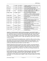


OPC90 Server
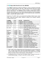
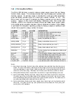
QUALITY VT_BOOL
Read/Write
Current
quality (see note 5) of Bailey values
(0-good, 1-bad).
HI_ACT
VT_BOOL
Read
PV High alarm active indicator (see note 6).
LO_ACT
VT_BOOL
Read
PV Low alarm active indicator (see note 6).
DV_HI_ACT
VT_BOOL
Read
High deviation alarm active indicator (see
note 6).
DV_LO_ACT
VT_BOOL
Read
Low deviation alarm active indicator (see note
6).
MODE
VT_I2
Read/Write
Mode of this control loop expressed as 0 –
Manual, 1 – Auto, 2 – Cascade.
MODE_LOCK
VT_BOOL
Read/Write
Indicates locked into current mode when set.
PV VT_R4
Read/Write
Process
variable.
OUT
VT_R4
Read/Write
Control output (range is limited to –5.0 to
105.0).
OUT_TRACKING
VT_BOOL
Read/Write
Indicates output tracking when set.
RED_TAG
VT_BOOL
Read/Write
Device red tag indicator.
SP VT_R4
Read/Write
Set
point.
SP_TRACKING
VT_BOOL
Read/Write
Indicates set point tracking when set.
RI
VT_R4
Read/Write
Ratio index (only used for ratio station types).
AO_BYPASS
VT_BOOL
Read/Write
Indicates analog output bypass when set.
DS_BAD VT_BOOL
Read/Write
Indicates
bad digital control station (Bailey
hard DCS station) when set.
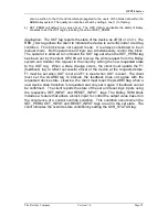
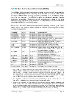
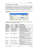
1.) Make sure the block number attribute is unique with respect to the other AOL, DOL, ODD,
ORCM, ORMC, ORMSC and OSTN OPC90 blocks associated with the same OPC90
DEVICE block. The block number attribute must also be defined within the range of 1 to
maximum number of allowed outputs set up within the associated OPC90 DEVICE block.
The Bailey system will receive data from this block at the ring and node address of the Bailey
CIU interface, module two and block number defined by the block attribute.
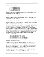
2.) The engineering units code is a number used by the Bailey consoles to index into a table of
text strings representing the engineering units of the process variable and set point values.
3.) The station type code is a number used by the Bailey consoles to identify characteristics of
its station faceplate display. Valid codes are: 1 – Basic with SP, 2 – Ratio, 4 – Cascade, 8 –
Basic without SP and 16 – Basic with Bias.
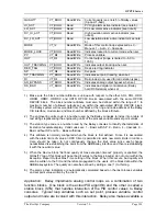
4.) This attribute is normally configured when the block is first defined. Since it is associated
with the alarm limits of value an OPC Client is permitted to write new alarm limits in run time.
Care should be taken to not continuously change the limit value since each change
necessitates dis-establishing the point from the ABB Bailey interface and than re-establishing
it with the new limit value.
5.) When the Device block “Set bad quality of max exception timeout” property is enabled, the
QUALITY tag of this block will be set bad if writes to the block input(s) do not occur within the
Exception Report Output Max Time setting of the block. When this occurs, bad quality will
also be written to the CIU and therefore propagated to the users of the block data within the
ABB Bailey system. The quality can also be set bad by writing a one (1) to this tag.
6.) The alarm active indicators are automatically calculated based on the last process variable
and set point value written by the client.
Application:
Bailey implements analog control loops as a combination of two
function blocks. One block is the actual PID algorithm and the other is called a
station block (STN) that handles interaction of the PID control values to Bailey
consoles. Typical loop variables such as set point, process variable, control
output and mode are involved with this interaction. Bailey also makes available a
The RoviSys Company
Version 7.0
Page 101


