


4-5
Level Controller Configuration
CONFIGURE THE
CONTROLLER
These tasks configure how you want to control the liquid level process.
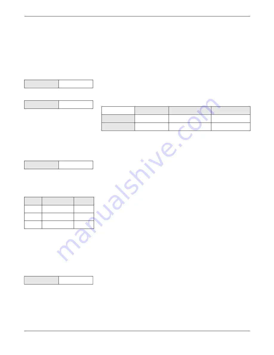
Set Range Values
The Level Controller range is determined by user-entered range points:
Lower Range Value (LRV) and Upper Range Value (URV). The level
measurement span (URV – LRV) must be within the level variable
limits.
Level LRV
Set LRV to the normal low operating point of the process, or the bottom
of the tank.
Level URV
Set URV to the normal high operating point of the process, or the top of
the vessel.
Set Control Type
The user can select from four different Control Types. The selected
control method is used to adjust the control signal to maintain the level
at the target setpoint.
Control Type
P (Proportional control only)
. This algorithm only uses the P (gain)
factor for the control algorithm. Manual Bias is also used in conjunction
with a time-decay balance term to provide for bumpless mode transfers.
PI (Proportional plus Integral control)
. This algorithm use the P (gain)
and I (Reset) factors for the control algorithm. Manual Bias and
Adaptive Bias are not used for this control type.
Quick Lookup Table
PID (Proportional plus Integral plus Derivative control)
. This
algorithm use the P (gain), I (reset), and D (derivative) factors for the
control algorithm. Manual Bias and Adaptive Bias are not used for this
control type.
PD (Proportional plus Derivative control)
. This algorithm use the P
(gain) and D (derivative) factors for the control algorithm. Manual Bias
is also used in conjunction with a time-decay balance term to provide for
bumpless mode transfers.
Factory Default:
PID
Valid Options:
P, PI, PID, PD
Set Control Action
(Direct, Reverse)
Control Action
The user can set the action of the control output to either direct or
reverse acting output to accommodate processes with negative or
positive gains. In direct action, the controller output increases when the
PV exceeds the setpoint. In reverse action, the controller output
decreases when the PV exceeds the setpoint.
Factory Default:
Reverse
Valid Options:
Direct, Reverse
HART Comm.
6, 1, 1, 4, 2
HART Comm.
6, 1, 1, 4, 1
Level Variable
Factory Default
Valid Range
Recommendation
LRV
0 inches
level_lsl to level_usl
Bottom of Tank (0)
URV
level_url
level_lsl to level_usl
Top of Tank
HART Comm.
6, 2, 1, 1, 1
Abbrev.
Algorithm Term
a.k.a.
P
Proportional
Gain
I
Integral
Reset
D
Derivative
Rate
HART Comm.
6, 2, 1, 1, 2
Summary of Contents for 3095
Page 2: ......
Page 4: ......
Page 8: ...viii ...
Page 10: ...Rosemount Model 3095 Multivariable Level Controller 1 2 ...
Page 42: ...Rosemount Model 3095 Multivariable Level Controller 3 10 ...
Page 74: ...Rosemount Model 3095 Multivariable Level Controller 5 18 ...
Page 98: ...Rosemount Model 3095 Multivariable Level Controller B 4 ...
Page 101: ...C 3 Approval Drawings FIGURE 3 1 continued 3095 1025A02A ...
Page 102: ...Rosemount Model 3095 Multivariable Level Controller C 4 FIGURE 3 1 continued 3095 1025A03A ...
Page 103: ...C 5 Approval Drawings FIGURE 3 2 Index of I S F M for 3095 3095 1020A01A ...
Page 104: ...Rosemount Model 3095 Multivariable Level Controller C 6 FIGURE 3 2 continued 3095 1020A02A ...
Page 105: ...C 7 Approval Drawings FIGURE 3 2 continued 3095 1020A03A ...
Page 106: ...Rosemount Model 3095 Multivariable Level Controller C 8 FIGURE 3 2 continued 3095 1020A04A ...
Page 107: ...C 9 Approval Drawings FIGURE 3 2 continued 3095 1020A05A ...
Page 108: ...Rosemount Model 3095 Multivariable Level Controller C 10 FIGURE 3 2 continued 3095 1020A06A ...
Page 110: ...Rosemount Model 3095 Multivariable Level Controller C 12 FIGURE 3 3 continued 3095 1024A02A ...
Page 111: ...C 13 Approval Drawings FIGURE 3 3 continued 3095 1024A03A ...
Page 113: ...C 15 Approval Drawings FIGURE 3 4 continued 3095 1021A02A ...
Page 114: ...Rosemount Model 3095 Multivariable Level Controller C 16 FIGURE 3 4 continued 3095 1021A03A ...


