


2-21
Level Controller Overview and Installation
Check for Leaks
Check all process penetrations for leaks. Process leaks can cause death
or serious injury.
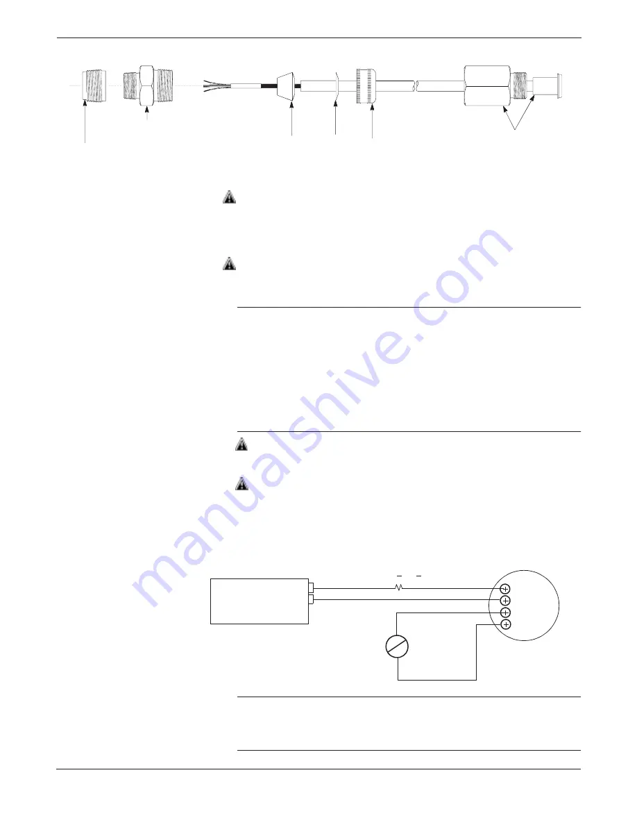
Field Wiring
(Power and Signal)
Make field wiring connections (see Figure 2-12). These connections
provide both power and signal wiring.
For
all
installations, wiring connections must be made in accordance
with local or national installation codes such as the NEC NFPA 70.
Make sure only qualified personnel perform these procedures.
NOTES
• Do not run field wiring in conduit or open trays with other power
wiring, or near heavy electrical equipment.
• Field wiring need not be shielded, but use twisted pairs for best
results.
• To ensure communication, wiring should be 24 AWG or larger
and not exceed 5,000 feet (1,500 meters).
• For connections in ambient temperatures above 140 °F (60 °C),
use wiring rated for at least 194 °F (90 °C).
1. Remove the cover on the side marked FIELD TERMINALS on the
electronics housing. Do not remove the instrument cover in
explosive atmospheres when the circuit is alive.
2. Connect the lead that originates at the positive side of the power
supply to the terminal marked “+ PWR.” Be sure to include loop
resistance. Avoid contact with leads and terminals.
3. Connect the lead that originates at the negative side of the power
supply to the terminal marked “– PWR.”
4. Connect the I/P or other actuator device to “+ OUT” and “– OUT.”
NOTE
If you are not connecting the OUT terminals to an actuator device,
you must install a jumper wire between “+ OUT” and “– OUT” for
proper operation.
Compression Fitting
Rubber Bushing
(Slide stop to edge
of armored cable)
Washer
Cap
RTD Cable Adapter
and Connector
(Connects to Model 3095 MV)
3
095
-0
020
D
01
A
¾ to ½–in. NPT Adapter
(Screws into RTD Connection Head)
1100
V
> R
L
> 250
V
+
–
I
P
FIGURE 2-12. Field
Wiring Connections.
+
–
+
–
PWR
OUT
Level
Controller
User-Provided
Power Supply
(see page 2-18)
–
+
Actuator
Device
Summary of Contents for 3095
Page 2: ......
Page 4: ......
Page 8: ...viii ...
Page 10: ...Rosemount Model 3095 Multivariable Level Controller 1 2 ...
Page 42: ...Rosemount Model 3095 Multivariable Level Controller 3 10 ...
Page 74: ...Rosemount Model 3095 Multivariable Level Controller 5 18 ...
Page 98: ...Rosemount Model 3095 Multivariable Level Controller B 4 ...
Page 101: ...C 3 Approval Drawings FIGURE 3 1 continued 3095 1025A02A ...
Page 102: ...Rosemount Model 3095 Multivariable Level Controller C 4 FIGURE 3 1 continued 3095 1025A03A ...
Page 103: ...C 5 Approval Drawings FIGURE 3 2 Index of I S F M for 3095 3095 1020A01A ...
Page 104: ...Rosemount Model 3095 Multivariable Level Controller C 6 FIGURE 3 2 continued 3095 1020A02A ...
Page 105: ...C 7 Approval Drawings FIGURE 3 2 continued 3095 1020A03A ...
Page 106: ...Rosemount Model 3095 Multivariable Level Controller C 8 FIGURE 3 2 continued 3095 1020A04A ...
Page 107: ...C 9 Approval Drawings FIGURE 3 2 continued 3095 1020A05A ...
Page 108: ...Rosemount Model 3095 Multivariable Level Controller C 10 FIGURE 3 2 continued 3095 1020A06A ...
Page 110: ...Rosemount Model 3095 Multivariable Level Controller C 12 FIGURE 3 3 continued 3095 1024A02A ...
Page 111: ...C 13 Approval Drawings FIGURE 3 3 continued 3095 1024A03A ...
Page 113: ...C 15 Approval Drawings FIGURE 3 4 continued 3095 1021A02A ...
Page 114: ...Rosemount Model 3095 Multivariable Level Controller C 16 FIGURE 3 4 continued 3095 1021A03A ...


