background image

22

6  Operation Guide [Cutting Section]

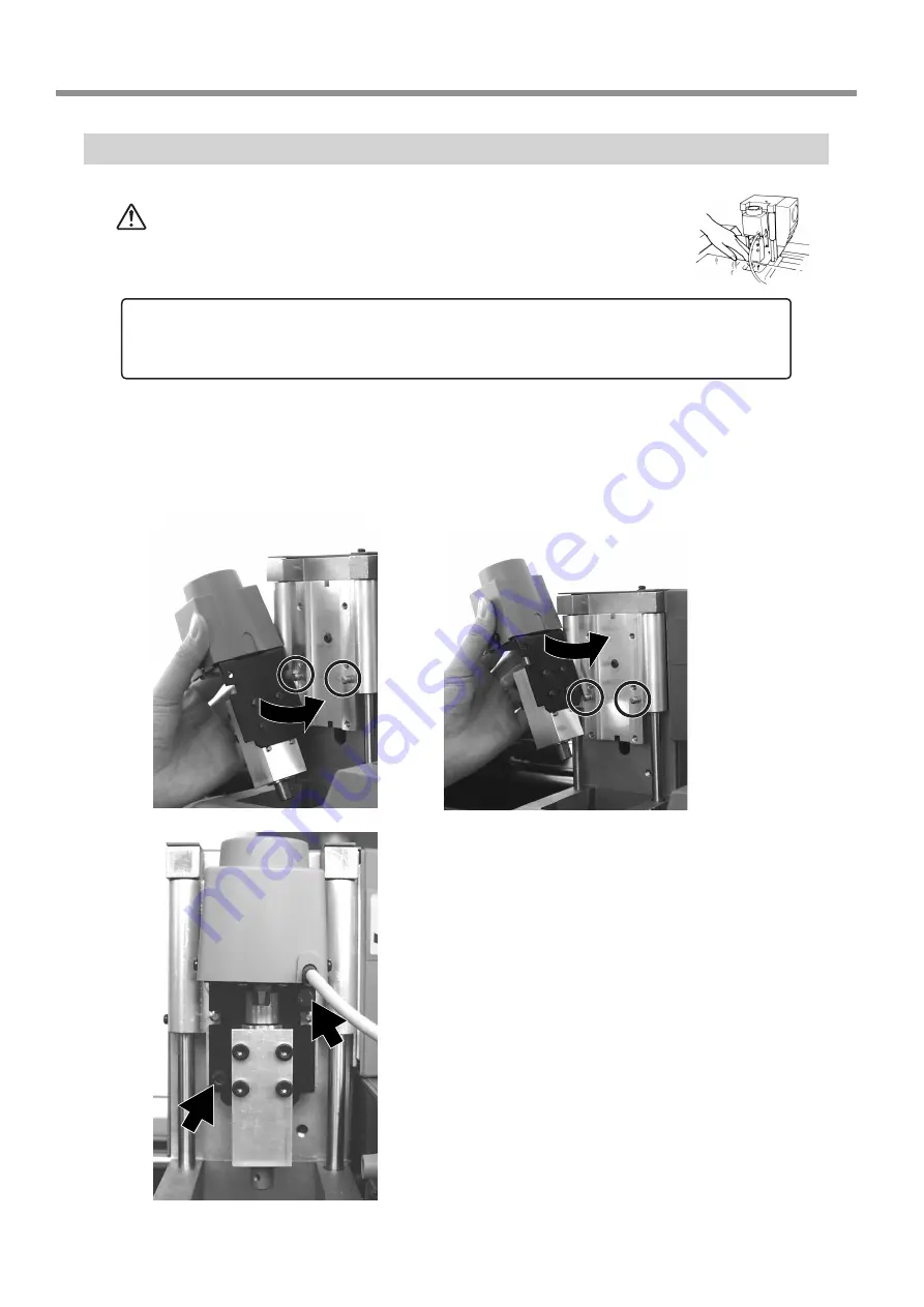
Attach the Spindle Unit

 CAUTION


During cutting or scanning, keep hands away from the cutting 

tool and the probe.

Doing so may result in injury.

Before attaching the spindle unit, make sure the power to the Modela is switched off.

Engage the notch on the spindle unit with the area of the carriage shown in the figure, and 

press down gently with your hand.

Insert the cap screws at the locations shown in the figure, 

and tighten them loosely using the included hexagonal 

wrench (size : 3 mm). After attaching all two screws in this 

way, tighten them securely.

NOTICE

Attach the spindle unit securely so that it does not come loose during cutting.

When mounting at the low

position

When mounting at the 

high position

Summary of Contents for MODELA MDX-15

Page 1: ... subject to change without notice The operation manual and the product have been prepared and tested as much as possible If you find any misprint or error please inform us Roland DG Corp assumes no responsibility for any direct or indirect loss or damage which may occur through use of this product regardless of any failure to perform on the part of this product Roland DG Corp assumes no responsibi...

Page 2: ...n void the users authority to operate this equipment Use only I O cables that have been designed and manufac tured specifically for this device For Canada NOTICE This Class A digital apparatus meets all requirements of the Canadian Interference Causing Equipment Regulations AVIS Cet appareil numérique de la classe A respecte toutes les exigences du Règlement sur le matériel brouilleur du Ca nada W...

Page 3: ...7 Powering ON 28 Perform Surfacing 28 Perform Cutting 33 Pausing or stopping operation 33 When Cutting is Finished 34 7 Operation Guide Scanning Section 36 Step 1 Attach the Sensor Unit 36 Step 2 Load the Object to Be Scanned on the MODELA 38 Step 3 Attach the Front Cover 40 Step 4 Powering ON 40 Step 5 Setting Scanning Conditions and Starting Scanning 41 Step 6 Setting the scanning area 42 Step 7...

Page 4: ...e registered trademarks of Intel Corporation in the United States AutoCAD is registered trademark of Autodesk Inc IBM is trademark of International Business Machines Corporation Other company names and product name are trademarks or registered trademarks of their respective holders 12 Specifications 68 Main Unit Specifications 68 Modeling Functions 68 Scanning Functions 68 Interface Specification ...

Page 5: ...ing in injury Do not use with any power supply other than the dedicated AC adapter Use with any other power supply may lead to fire or electrocution Use only with the power cord included with this product Use with other than the included power cord may lead to fire or electrocution Ground the unit with the ground wire Failure to do so may result in risk of electrocu tion in the event of a mechanic...

Page 6: ...n injury Do not allow children to operate without adult supervision or operate within reach of young children Doing so may result in injury CAUTION During cutting or scanning do not place hands near the cutting tool or the probe Doing so may result in injury While the power is on do not remove the spindle unit from the carriage Doing so may result in injury Store clay out of the reach of children ...

Page 7: ...ical power supply that does not meet the ratings displayed on the AC adapter In addition to the WARNING and CAUTION symbols the symbols shown below are also used NOTICE Indicates information to prevent machine breakdown or malfunction and ensure correct use Indicates a handy tip or advice regarding use During cutting or scanning keep hands away from the cutting tool and the probe Model name 5 To E...

Page 8: ...ng the size or make use of a natural shape as part of another design Cutting a shape Engraving Creating data from a shape Use software to create a three dimen sional object Enter the parameters for cutting the three dimensional object cutting parameters Perform cutting Finished result Use software design a line drawing Enter the parameters for engraving en graving parameters Perform engraving Fini...

Page 9: ...ng pins 3 2 diameter 3 mm 0 118 in length 20 mm 0 787 in One spare Double sided tape 1 Clay 1 MDX 20 15 User s Manual 1 The configuration of the MDX 15 differs but the at tachment method is the same 1 Do not discard the included item box containing the spindle unit and sensor unit It is needed to hold the unused unit while Modela is in operation 2 The positioning pin is used when performing double...

Page 10: ...of the MDX 15 differ from the figure Front Rear NOTICE Do not touch the wire with the hands Except when repacking the unit do not attempt to move the table or carriage by hand Carriage Jack Work plate Table Switch Panel MODELING MODE LED SCANNING MODE LED STANDBY key VIEW LED VIEW key TOOL UP key TOOL DOWN key AC adapter jack Serial connector Wire ...

Page 11: ...may result in falling of the unit leading to injury Connecting the AC Adapter and Power Cord Connect in the order of the numbers shown in the figure NOTICE Never install this unit in any of the following situations as it could result in damage Places where the installation surface is unstable or not level Places with excessive electrical noise Places with excessive humidity or dust Places with poo...

Page 12: ...computer then use an optionally available XY RS 14 34 cable or equivalent A straight cable such as modem cable will not work Make sure the power to the computer and the MODELA is switched off before attempting to connect the cables IBM PC or PC compatible Serial cable XY RS 34 or equivalent Serial connector ...

Page 13: ...und text with just a single click a handy feature when making nameplates You can use MODELA to cut three dimensional text and save data in three dimensional DXF files Virtual MODELA This simulates tool movement before performing cutting with MODELA You can use it to check the finished shape as well as things like whether the cutting depth is suitable and how much time cutting will take This can re...

Page 14: ...ick the button To view the manual click the button TherearemanualsinPDFformatfortheprogramsthatthe button references Acrobat Reader is required to view PDF files If there are programs you don t want to install then clear their check boxes before you click Install The Setup program starts Follow the messages to carry out setup and finish setting up the program When the setup for one program finishe...

Page 15: ...ribe operation of the MDX 20 If you re using the MDX 15 then where MDX 20 ap pears in the text read MDX 15 instead Driver for Windows 95 98 Me Click Start Settings Printer to open the Printer folder Right click on the Roland MODELA MDX 20 icon then click Properties The Roland MODELA MDX 20 Properties dialog box appears Click the Details tab At Print to the following port s choose an unused port ot...

Page 16: ...k Printers and Faxes Right click on the Roland MODELA MDX 20 icon then click Properties The Roland MODELA MDX 20 Properties dialog box appears Click the Ports tab For Port choose an unused port other than COM1 Click Configuration Port Windows NT 4 0 go to step 4 Windows 2000 XP go to step 5 Click the port you chose in step 3 then click Settings Make the settings for the following communication par...

Page 17: ...n where MDX 20 ap pears in the text read MDX 15 instead MODELA Player Click Start and point to Programs Point to Roland MODELA and click MODELA Player From the Options menu click Machines The Model Selection dialog box appears Click MDX 20 then click OK From the File menu click Print Setup The Print Setup dialog box appears Click the drop down arrow for the name and click Roland MODELA MDX 20 Then...

Page 18: ... From the File menu click Print Setup The Print Setup dialog box appears If You re Using Windows NT4 0 2000 XP If the printer port for the Windows driver and the communication port for Dr PICZA are set to the same port you cannot use Dr PICZA To perform scanning you need to temporarily set the Windows driver printer port to a different port After you finish scanning return the setting for the Wind...

Page 19: ...e Click Start Point to Roland 3D Engrave and click 3D Engrave From the Cut menu click Machines The Model Selection dialog box appears Click MDX 20 then click OK From the File menu click Output Device Setup The Print Setup dialog box appears Click the drop down arrow for the name and click Roland MODELA MDX 20 Then click OK ...

Page 20: ...n an image area that contains an explanation displays the explanation Tip When the pointer moves over green underlined text it changes to a pointing hand When the pointer moves over a location where an explanation is in cluded it changes to a pointing hand When there s a button on screen Clicking in the upper right corner of the window makes the mouse pointer change to a question mark You can then...

Page 21: ...x appears Choose the desired file and click Open 2 Set the Cutting Parameters The cutting parameters are the parameters for cutting the solid object For MODELA Player make these settings Cutting surface The surface of the solid object to be cut Size The size of the finished object Depth The depth of cutting Material The composition of the workpiece to be cut Cutting process The stage of cutting To...

Page 22: ...er a value from the keyboard Clicking Resize makes it possibletospecifyaratiofor the dimensions C Set the maximum cut ting depth Make the setting for the maximum cutting depth Drag the spin dial up or down or click on a number and enter a value from the keyboard Clicking Center sets the depth at a location propor tional to the height D Tool diameter Material Finish Tool Setthetypeanddiameterofthet...

Page 23: ...int Preview Virtual MODELA starts The cutting data from MODELA Player is imported into Virtual MODELA An animated display of tool movement appears and the shape after cutting is gradually produced For more information on how to operate Virtual MODELA see the help for Virtual MODELA 4 Save the file From the File menu click Save As The Save As dialog box appears Choose where to save the file type a ...

Page 24: ...e the notch on the spindle unit with the area of the carriage shown in the figure and press down gently with your hand Insert the cap screws at the locations shown in the figure and tighten them loosely using the included hexagonal wrench size 3 mm After attaching all two screws in this way tighten them securely NOTICE Attach the spindle unit securely so that it does not come loose during cutting ...

Page 25: ...nt the base as well Make the layout the same as for actual cutting Move the spindle to its highest point When viewed from the side if the tip of the tool is lower than the surface of the work piece remount the spindle unit at the higher location Tube Make sure it is at the base of the cord Spindle unit Carriage Spindle unit Carriage Approximately 80 6 mm 3 3 16 in Spindle operating range 60 5 mm 2...

Page 26: ...ndle It s not necessary to remove the whole spindle unit While supporting the spindle by hand remove the screws at the four places in the figure Pull out the spindle from below to remove it Insert the cutting tool into the spindle The cutting tool must not be inserted beyond the shank NOTICE Attach the cutting tool securely so that it does not come loose during cutting Spindle Spindle Cutting tool...

Page 27: ... are in place While supporting the spindle by hand tighten securely About the Length of Tool Extending Beyond the Spindle Tip Care is required regarding the length of tool extending beyond the spindle for the following reasons If too short the tool tip will not reach the desired depth If too long the tool may strike the workpiece when the tool is raised The restricted tool length varies according ...

Page 28: ...l Remove the screws shown in the figure and detach the work plate Bottom surface of the carriage Work plate surface 62 4 mm 2 7 16 in Workpiece thicker than this value cannot be loaded In actual use the thickness of the load able workpiece varies according to the length of the mounted tool and the thick ness of the base MDX 20 203 2 mm 8 in MDX 15 152 4 mm 6 in MDX 20 152 4 mm 6 in MDX 15 101 6 mm...

Page 29: ...late Attach the Front Cover Attach the front cover If the cover is not attached the VIEW LED lights every 1 sec up and MODELA does not operate NOTICE Be sure to attach the front cover If not installed cuttings may scatter and enter nearby computers or other equip ment resulting in breakdown Workpiece Double sided tape The center of the hole at the lower left of the work plate is the suggested X an...

Page 30: ... CAUTION During cutting or scanning do not place hands near the cut ting tool or the probe Doing so may result in injury CAUTION Do not allow children to operate without adult supervision or operate within reach of young children Doing so may result in injury CAUTION Do not operate if a transparent cover is cracked or broken If the transparent cover at the front or the side of the unit is cracked ...

Page 31: ... to lower the cutting tool a little at a time When the tip touches the workpiece release the TOOL DOWN key After setting the reference point do not press theTOOL UP orTOOL DOWN keys 2 Verify the Cutting Position and Height When the Tool Is Lowered Use MODELA Player to move the MODELA tool then verify the following two points Object Cutting Position Make sure that the cutting position specified wit...

Page 32: ...ce Point If it is not cut then proceed to step 2 of 4 Perform Surfacing and perform surfacing To make the setting for the cutting position only without performing surfacing then click OK 3 Reset the Depth direction Reference Point In 2 verify the specified cutting position and the height when the tool is lowered if the tool cut the surface of the workpiece then you need to redo the setting Reset t...

Page 33: ...epth direction reference point has now been reset Lower the cutting tool at the four remaining corners with the new reference point and make sure that the workpiece is not cut See 2 Verify the Cutting Position and Height When the Tool Is Lowered in the previous section If the workpiece is cut then repeat steps 2 and 3 and set a new reference point When you view the loaded workpiece edge on from th...

Page 34: ...ection for Automatic To change the range drag the solid squares surrounding the shaded area or type in numerical values for Width and Length To change the location drag the shaded portion or type in numerical values for Lowerleft X Lowerleft Y Click Start to start surfacing When surfacing ends the depth direction reference point is set at the surface after surfacing When surfacing ends click OK ...

Page 35: ...Depending on the composition of the workpiece however finishing may not actual produce an attractive finish In such cases use a file or the like to work it by hand Click START to start cutting Pausing or stopping operation Press the VIEW key to quit the cutting operation To continue with cutting Press the VIEW key again To end cutting Stop sending data from MODELA Player Open the Printers folder W...

Page 36: ...re due to deterioration of the electrical insulation CAUTION Use a commercially available brush to remove metal cut tings Attempting to use a vacuum cleaner to take up metal cuttings may cause fire in the vacuum cleaner CAUTION When you re finished wash your hands to rinse away all cuttings Be sure to remove cuttings only after MODELA has finished cutting Press the STANDBY key to switch off the po...

Page 37: ...cially available brush to remove any metal cuttings that are exposed After removing the cuttings hold down the STANDBY key and switch off the power Other cuttings Detach the work plate and use a vacuum cleaner to take up any cuttings Lift up MODELA and also remove any cuttings that may have fallen underneath Unplug the power cord plug from the electrical outlet Metal cuttings Remove using a commer...

Page 38: ...sor unit with the area of the carriage shown in the figure and press down gently with your hand Insert the cap screws at the locations shown in the figure and tighten them loosely using the included hexagonal wrench size 3 mm After attaching all four screws in this way tighten them securely NOTICE Attach the sensor unit securely so that it does not come loose during cutting Perform installation an...

Page 39: ...e screw shown in the figure Pull the cover back to remove it Make sure the tube is at the position shown in the figure Insert the plug for the sensor unit into the jack Screw Cover Tube Make sure it is at the base of the cord Position the connector so the arrow points to the back of the unit and insert ...

Page 40: ...hed by the sensors Pressure may fluctuate depending on the composition of the object being scanned For instance it may not be possible to scan something like a fuzzy stuffed animal or rubber Depending on the shape you re scanning a maximum error equal to the radius of the probe 0 5 mm may occur Detaching the Sensor Unit Fit the cover onto the sensor unit as shown in the figure While gently pressin...

Page 41: ...rea for Dr PICZA The scale is in 10 mm 3 8 in units Maximum scanning area of the MODELA The maximum scanning area is shown in the figure MDX 20 203 2 mm 8 in MDX 15 152 4 mm 6 in MDX 20 152 4 mm 6 in MDX 15 101 6 mm 4 in Maximum scaning area 1 mm 0 0394 in 60 5 mm 2 3 8 in Work plate This space cannot be scanned When the shape has a flat bottom and is easy to secure in place When the bottom is une...

Page 42: ...Step 4 Powering ON NOTICE Before switching on the power to the MODELA turn on the computer Press the STANDBY key The STANDBY LED lights up The unit performs initial operation and stops and the SCANNING MODE LED lights up Press in all the way until flush Fit the cover plate into place from above so that it goes into the portion shown in the figure ...

Page 43: ... is already open Make the settings for X scan pitch and Y scan pitch Make the setting for Z bottom If you have made a clay base the height of the clay is taken to be the Z axis reference surface About scanning conditions and the scanning area Scanning area Scan path bidirectional scanning Scan points Cray Workpiece plate If you have made a clay base the height of the clay is taken to be the Z axis...

Page 44: ... scanning you need to temporarily set the Windows driver printer port to a different port After you finish scanning return the setting for the Windows driver to its original value Use the following examples as a guide to determine the amount of computer memory required to perform scanning The figures shown below are the amounts used by Dr PICZA alone They do not take into account the amounts used ...

Page 45: ... position on the object to be scanned During scanning if the sensor detects a position higher than the Z upper limit setting the setting is cleared and scanning continues with the greatest scan height of Dr PICZA as the Z upper limit After determining the scanning area click OK Check the scanning conditions in the Controller window one more time then click Scanning starts During scanning the senso...

Page 46: ... for detailed explanations of the various functions that are available Be sure to save the scanned data before starting to edit When you re done editing be sure to save your file When Scanning Is Finished CAUTION When not in use for several hours unplug the power cord plug from the electrical outlet Failure to do so may result in danger of shock electrocution or fire due to deterioration of the el...

Page 47: ...escanning Location of the Usage Guides The usage guides are found at the following locations View the following files directly from the CD ROM or copy the following files to your hard disk and read them from there Cutting Tips Document Cuttips Cuttip e pdf Scanning Tips Document Scantips Scatip e pdf Installing the Acrobat Reader Acrobat Reader is required to view PDF files If Acrobat Reader is no...

Page 48: ...g speed depth and pitch When sending data from MODELA Player or 3D Engrave to MODELA the data is sent to the driver s output port At this time all driver settings other than the port are ignored and do not affect cutting Display the Driver Setting Screen To make the settings for the driver open Properties You can use either of the two methods described below to open Prop erties Method 1 When you u...

Page 49: ...raving depth For Fill Pitch enter the tool diameter The values for settings other than Z Down Position and Fill Pitch are also suggested guidelines If the results of actual engraving are not as expected modify the values accordingly Lines are distinguished by color and parameters when engraving a line of the corresponding color are set Click the Tool tab Click the drop down arrow for Material then...

Page 50: ...s Administrators or Power Users ac count Display the Driver Setting Screen To make the settings for the driver open Properties You can use either of the two methods described below to open Prop erties Method 1 When you use this method to make the settings any changes you make in Properties also affect other Windows based programs Open the Printers folder Windows NT4 0 2000 Click Start Settings Pri...

Page 51: ...nter the Work Size Name then click OK Set the Engraving Parameters Make the settings for the composition of the workpiece to engrave and the engraving depth Choosing the composition sets engraving parameters suited to this engraving However Tool Down Position and Fill Tool Width are determined with no relation to composition and so they are set separately For Tool Down Position enter the engraving...

Page 52: ...ter the cutting in depth For Fill click Tool Width then enter the diameter of the tool tip MODELA 3D DESIGN This lets you choose a basic shape such as a cylinder or sphere and modify it to create a three dimensional object You can intuitively create solid objects with smooth curves Choose the basic shape Click The Primitives dialog box appears For items other than Tool Down Position and Fill Tool ...

Page 53: ...hown below 4 lines 7 lines 10 lines Manipulate Reference Lines to Make a Shape To change the height of a reference line position the pointer over the reference line and drag it up or down To change the size of the outer perimeter for a reference line position the pointer over the reference line and drag it to the left or right To change the shape of the outer perimeter right click on a reference l...

Page 54: ...nter the name of the file and click Save Description of Controls This opens new file This saves the data as a DXF file This opens an existing file This starts MODELA Player This saves the file overwriting the previous data This undoes the very last op eration This moves a reference lines up or down When is selected the location of the centerpoint moves up or down This zooms the screen in or out Th...

Page 55: ... TEXT This adds thickness to text to create three dimensional characters You can use the TrueType fonts registered in Windows as the font style for text Enter the Text Click the Edit text box then type in the text Make sure what you ve typed in is correct then click Go Determine the Font and Size of the Text Click the Font drop down arrow then click on a font name Click the Scale drop down arrow t...

Page 56: ...ext This rotates each individual character 90 degrees counterclockwise Thisdeterminestheroughnessofcurved portions of the text This makes the text italic This inverts the background color This makes the text bold MODELA Player For information on how to use MODELA Player see 6 Operation Guide Cutting Section Virtual MODELA You can use a tool path created with MODELA Player or 3D Engrave to verify t...

Page 57: ...screen Moving the Location Click then drag on the screen Description of Controls This creates a new uncut work piece This switches between adding and not adding color to the surface of the workpiece To specify a color click Options Surface Color This opens an existing cutting configuration file This restricts the 3D view range It also determines the print ing area when performing 2D simulation Res...

Page 58: ...ment of the tool with animation Dr PICZA For information on how to use Dr PICZA see 7 Operation Guide Scanning Section This section describes the controls for Dr PICZA This unhides and hides the controller window At the con troller window you can make the settings for the various scanning parameters These display the coordinates of the point chosen with the mouse pointer Clicking a start point and...

Page 59: ...Guide Driver for Windows NT 4 0 2000 XP Enter the Cutting Area From the File menu click Print Setup The Print Setup dialog box appears Make sure Roland MODELA MDX 20 is specified as the printer then click Properties The Roland MODELA MDX 20 dialog box appears Enter the size of the plate then click OK Next click OK to close the Printer Setup dialog box Thewhiteportionofthescreenistheengravingarea L...

Page 60: ...ters Changing the Size Rotating and Slanting Clicking again makes the pointers change to circles and diamonds Moving the Location You can freely change the size of the object by drag ging To retain the object s vertical horizontal aspect when you change its size hold down the Shift key while dragging Drag to change the horizontal size Drag to change the vertical size Drag to rotate the shape Drag ...

Page 61: ...g the previous data This draws the shapes This sends engraving data to MOD ELA This makes an entry frame for text This deletes the selected object and copies it to the clipboard This changes the chosen text string to line characters This copies the selected object to the clipboard This performs flat drag machining for the interior of a shape or text This copies the clipboard data to the screen The...

Page 62: ... on the Size of the Relief From the Relief menu click Relief Size The Relief Size dialog box appears Enter the size of the relief and the resolution the degree of detail of the relief then click OK Thescreenatrightappears Thewhiteareaofthescreenisthewhere you design the relief The screen displayed at this time is called the 2D screen It s the screen for typing in text and creating shapes Creating ...

Page 63: ...tright andathree dimensional view of the shape of the relief appears This is called the 3D screen and it displays the shape of the relief and the tool path You cannot edit shapes or text Enter the height of the bottom of the relief Enter the thickness of the relief These choose the configuration for pushing the object up or down These choose how to stack the relief This is for entering the directi...

Page 64: ...lick the When the tool path is created it appears in pink on the 3D screen Checking the Cutting Results If Virtual MODELA is installed and set up then before you perform actual cutting you can check the shape that will be pro duced after cutting on the screen From the File menu click Output Preview Virtual MODELA starts The cutting data from 3D Engrave is imported into Virtual MOD ELA An animated ...

Page 65: ...n al shape editing screen Thischangesthedisplaylocationofthe object Thismovesthescreendisplayto show areas outside the window which are not visible This switches to a solid three dimen sional display screen Display this screen when you want to check a tool path or the shape of a relief This changes the perspective of the relief when you drag the screen This is available only during 3D screen This ...

Page 66: ...per la raccolta differenziata non buttare nel cestino dei rifiuti casalinghi Este producto debe devolverse al centro de reciclaje más cercano a su domicilio para su correcta eliminación No lo tire a la basura Deite fora separadamente este produto no seu centro de reciclagem local Não o deite fora no seu caixote do lixo Lever dit product in bij een lokaal afvalverzamelpunt NIET met normaal huishoud...

Page 67: ... Ten Times Per Second Was the power switched on in the correct sequence First turn on the computer then turn on MODELA This indicates a communications error Switch off the power then check the cable connections and the port setting for the driver Was the computer restarted When the computer has been restarted switch the power to the MODELA off wait a few seconds then switch it back on All LEDs Fla...

Page 68: ... the same error display occurs consult your authorized Roland dealer or service center Unexpected Program Operation I can t open a file Does the program you re using support the format of the file you re trying to open Check the program and the file format and make sure the combination is supported There is not enough memory available for processing Close all other applications or restart Computer...

Page 69: ...Be Copied Unauthorized reproduction of a copyrighted item for any purpose other than personal use may be a violation of copyright Roland DG Corp will not be responsible for any violation of third party copyright by any article made through use of this product ...

Page 70: ... F Operation humidity 35 to 80 no condensation Accessories AC adapter 1 power code 1 Roland Software Package CD ROM 1 spindle unit 1 sensor unit 1 cap screw M4x15 4 tool 1 set screw M3x3 2 double sided tape 1 front cover 1 hexagonal wrench size 3 mm 1 hexagonal wrench size 1 5 mm 1 positioning pins 3 clay 1 MDX 20 15 user s manual 1 Modeling Functions Tool chuck 6 mm or 1 8 in tool chuck included ...

Page 71: ...ission Transmission speed 9600 bps Parity Check None Data Bits 8 bits Stop Bits 1 bits Handshake Hardware Serial connector RS 232C Signal number Terminal number Signal number Pin connection NC 25 13 NC NC 24 12 NC NC 23 11 NC NC 22 10 NC NC 21 9 NC DTR 20 8 NC NC 19 7 SG NC 18 6 DSR NC 17 5 CTS NC 16 4 RTS NC 15 3 RXD NC 14 2 TXD 1 FG ...

Page 72: ... which the backup copy of the Software is recorded does not belong to the Company 4 Forbidden items 1 This copy of the Software or a backup copy of the Software must not be used on multiple computers at the same time on a network the Internet or on other computers through any other means of distribution 2 The Software shall not be reverse engineered decompiled or reverse assembled 3 The rights to ...

Reviews: