Using Explicit Messaging
6-29
PowerFlex® 755 Drive Embedded EtherNet/IP Adapter User Manual
Publication 750COM-UM001A-EN-P
SLC 500 Example Scattered Write Request Data
In this example, we use the F105: data table addresses to store the
request values to be written to these 32-bit REAL (floating point)
parameters:
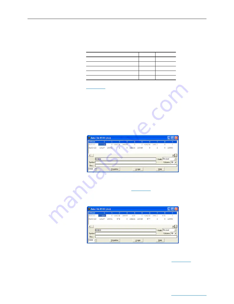
shows the parameter values which, in this example, have
been converted using a CPW (Copy Word) instruction—one for each
value—to correctly write their values. The CPW instruction separates
the 32-bit REAL (floating point) value (for example, F105:0 which
contains 11.1 seconds) into two 16-bit integers (for example N100:2
and N100:3). While the values in the 16-bit integer registers represent
the actual values being written in the 32-bit floating point registers, they
will not appear correct, but the message will properly decode them.
Figure 6.33 Example Scattered Write Request Unconverted Data File
To complete message configuration, the numbers of the parameters
being written to must now be entered in the appropriate N100: data
table registers as shown in
for this example.
Figure 6.34 Example Scattered Write Request Unconverted Data File with
Entered Parameters
SLC 500 Example Scattered Write Response Data
In this example, we use the data table addresses in
the response values that were written to the requested drive parameters.
Values of “0” indicate no errors occurred.
PowerFlex 750-Series Drive Parameter Address
Write Value
536 - [Accel Time 2]
F105:0
11.1 Sec.
538 - [Decel Time 2]
F105:1
22.2 Sec.
575 - [Preset Speed 5]
F105:2
33.3 Hz.
576 - [Preset Speed 6]
F105:3
44.4 Hz.
577 - [Preset Speed 7]
F105:4
55.5 Hz.


