


Rockwell Automation Publication 520-UM001K-EN-E - August 2021
223
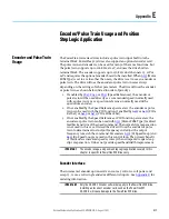
Appendix E Encoder/Pulse Train Usage and Position StepLogic Application
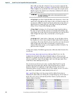
[Stp Logic Time x] are the
parameters that define the time the drive
will remain in each corresponding step if that step is time-based. For example,
if
[Stp Logic Time 2] is set to 5.0 seconds and that step is time-based, the
drive will remain in Step 2 for 5.0 seconds. Note that this is the total time in
that step, not the time at that position. Therefore, it will include the time
needed to accelerate, run, and decelerate to that position.
...
[Stp Logic x] are the parameters that
allow additional flexibility and
control various aspects of each step when a positioning mode is selected that
utilizes the StepLogic functions. Note that in Positioning mode these
parameters have a different function than when used for normal velocity Step
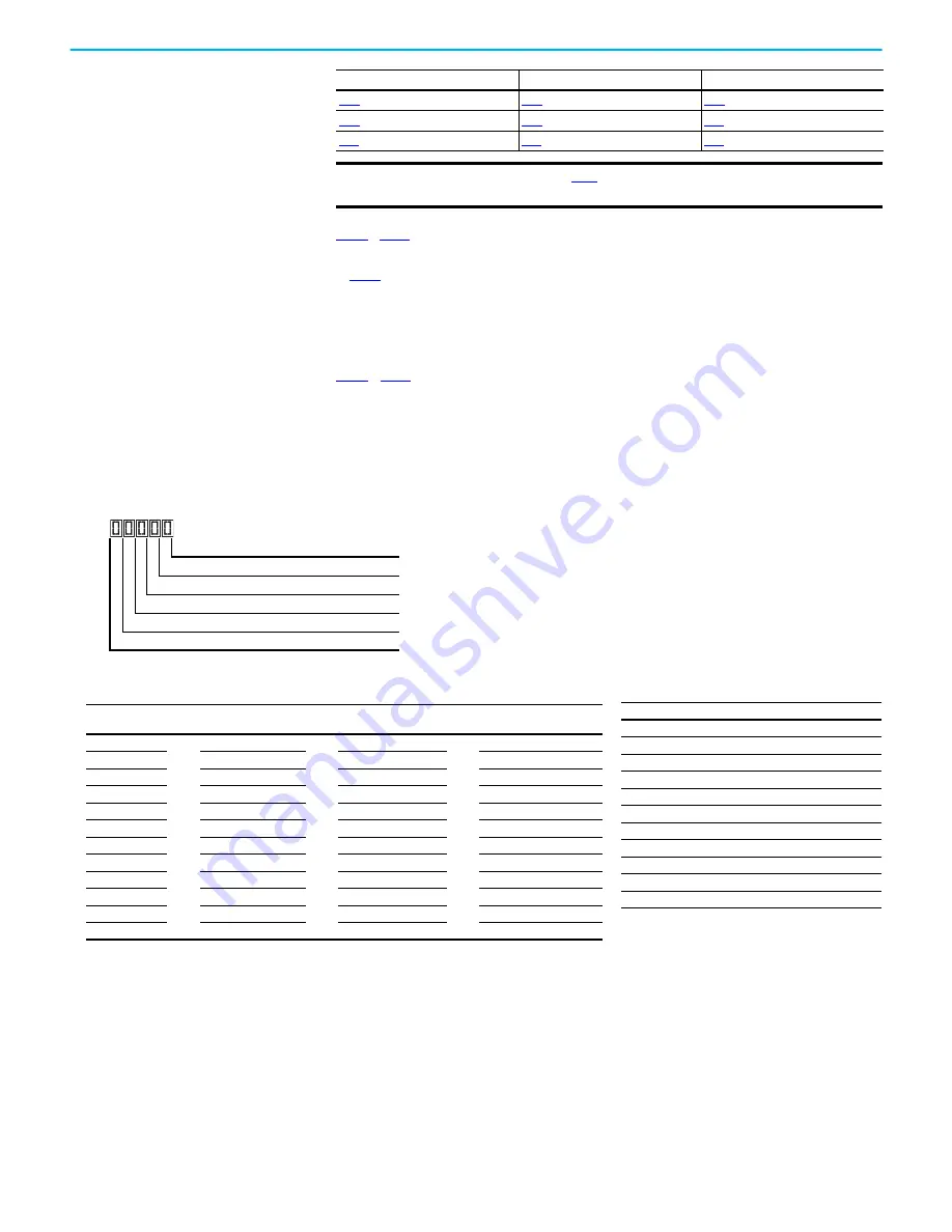
Logic. Each of the 4 digits controls one aspect of the each position step. The
following is a listing of the available settings for each digit:
[Stp Logic 5]
[Preset Freq 6]
[Stp Logic 6]
[Step Units 6]
[Preset Freq 7]
[Stp Logic 7]
[Step Units 7]
IMPORTANT
[Preset Freq 0] is 0.00 Hz. This value needs to
be changed or the drive will not be able to move during Step 0.
Frequency Source
Step Source
Position Source
Logic for next step
Digit 1
Logic to jump to a different step
Digit 2
Different step to jump
Digit 3
Step settings
Digit 4
Not Used
Velocity Control Settings (Digit 4)
Required
Setting
Accel/Decel
Param. Used
StepLogic
Output State
Commanded
Direction
0
Accel/Decel 1
Off
FWD
1
Accel/Decel 1
Off
REV
2
Accel/Decel 1
Off
No Output
3
Accel/Decel 1
On
FWD
4
Accel/Decel 1
On
REV
5
Accel/Decel 1
On
No Output
6
Accel/Decel 2
Off
FWD
7
Accel/Decel 2
Off
REV
8
Accel/Decel 2
Off
No Output
9
Accel/Decel 2
On
FWD
A
Accel/Decel 2
On
REV
b
Accel/Decel 2
On
No Output
Settings (Digit 3)
Setting
Description
0
Jump to Step 0
1
Jump to Step 1
2
Jump to Step 2
3
Jump to Step 3
4
Jump to Step 4
5
Jump to Step 5
6
Jump to Step 6
7
Jump to Step 7
8
End Program (Normal Stop)
9
End Program (Coast to Stop)
A
End Program and Fault (F2)
Summary of Contents for Allen-Bradley PowerFlex 520 Series
Page 8: ...8 Rockwell Automation Publication 520 UM001K EN E August 2021 Table of Contents Notes ...
Page 68: ...68 Rockwell Automation Publication 520 UM001K EN E August 2021 Chapter 2 Start Up Notes ...
Page 236: ...236 Rockwell Automation Publication 520 UM001K EN E August 2021 Appendix F PID Set Up Notes ...
Page 270: ...270 Rockwell Automation Publication 520 UM001K EN E August 2021 Index Notes ...