


Rockwell Automation Publication 520-UM001K-EN-E - August 2021
163
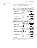
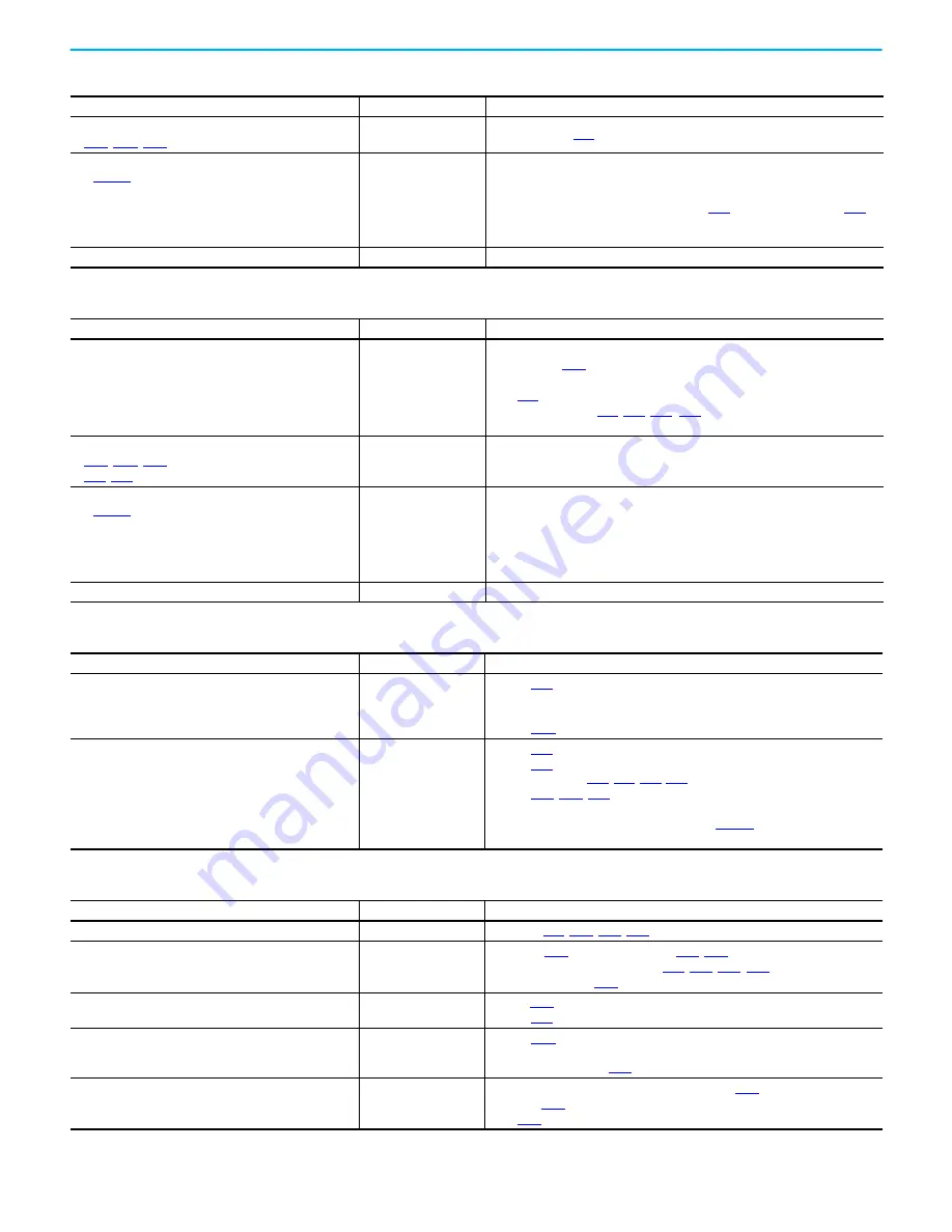
Chapter 4 Troubleshooting
Incorrect programming.
•
[Start Source x] is set incorrectly.
None
Check setting for
[Control Source].
Incorrect input wiring.
See
for wiring examples.
• 2 wire control requires Run Forward, Run Reverse or Jog
input.
• 3 wire control requires Start and Stop inputs
• Stop input is always required.
None
• Wire inputs correctly and/or install jumper.
• If the PowerFlex 525 Safe Torque Off function is used, verify that inputs are active.
• If 2-wire or 3-wire mode is used, verify that
[DigIn TermBlk 03] are set properly.
Incorrect sink/source jumper setting.
None
Set switch to match wiring scheme.
Motor does not Start (Continued)
Cause(s) (Continued)
Indication
Corrective Action
Drive does not Start from Start or Run Inputs wired to the terminal block
Cause(s)
Indication
Corrective Action
Drive is Faulted
Flashing red status light
Clear fault.
• Press Stop if
[Stop Mode] is set to a value between “0” and “3”.
• Cycle drive power.
• Set
[Fault Clear] to 1 “Reset Fault” or 2 “Clear Buffer”.
• Cycle digital input if
[DigIn TermBlk xx] is set to
13 “Clear Fault”.
Incorrect programming.
•
[Start Source x] is set incorrectly.
•
[DigIn TermBlk 02/03] is set incorrectly.
None
Check parameter settings.
Incorrect input wiring.
See
for wiring examples.
• 2 wire control requires Run Forward, Run Reverse or Jog
input.
• 3 wire control requires Start and Stop inputs
• Stop input is always required.
None
• Wire inputs correctly and/or install jumper.
• If the PowerFlex 525 Safe Torque Off function is used, verify that inputs are active.
Incorrect sink/source jumper setting.
None
Set switch to match wiring scheme.
Drive does not respond to changes in speed command
Cause(s)
Indication
Corrective Action
No value is coming from the source of the command.
The drive “Run” indicator
is lit and output is 0 Hz.
[Control Source] for correct source.
• If the source is an analog input, check wiring and use a meter to check for presence
of signal.
[Commanded Freq] to verify correct command.
Incorrect reference source is being selected by remote
device or digital inputs.
None
[Control Source] for correct source.
[Dig In Status] to see if inputs are selecting an alternate source.
,
[DigIn TermBlk xx].
[Speed Referencex] for the source of the speed
reference. Reprogram as necessary.
• Review the Speed Reference Control chart on
• Verify communications if used.
Motor and/or drive will not accelerate to commanded speed
Cause(s)
Indication
Corrective Action
Acceleration time is excessive.
None
[Accel Time x].
Excess load or short acceleration times force the drive into
current limit, slowing or stopping acceleration.
None
• Compare
[Output Current] with
[Current Limit x].
• Remove excess load or reprogram
,
• Check for improper
Speed command source or value is not as expected.
None
• Verify
[Commanded Freq].
[Control Source] for the proper Speed Command.
Programming is preventing the drive output from
exceeding limiting values.
None
[Maximum Freq] to ensure that speed is not limited by
programming.
[Speed Ratio].
Torque performance does not match motor characteristics. None
• Set motor nameplate full load amps in parameter
[Motor NP FLA].
• Perform
[Autotune] “Static Tune” or “Rotate Tune” procedure.
• Set
[Torque Perf Mode] to 0 “V/Hz”.
Summary of Contents for Allen-Bradley PowerFlex 520 Series
Page 8: ...8 Rockwell Automation Publication 520 UM001K EN E August 2021 Table of Contents Notes ...
Page 68: ...68 Rockwell Automation Publication 520 UM001K EN E August 2021 Chapter 2 Start Up Notes ...
Page 236: ...236 Rockwell Automation Publication 520 UM001K EN E August 2021 Appendix F PID Set Up Notes ...
Page 270: ...270 Rockwell Automation Publication 520 UM001K EN E August 2021 Index Notes ...