


204
Rockwell Automation Publication 520-UM001K-EN-E - August 2021
Appendix C RS485 (DSI) Protocol
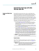
Network Wiring Diagram Example
Only pins 4 and 5 on the RJ45 plug should be wired. The other pins on the
PowerFlex 520-series drive’s RJ45 socket must not be connected because they
contain power, etc. for other Rockwell Automation peripheral devices.
Wiring terminations on the master controller will vary depending on the
master controller used and “TxRxD+” and “TxRxD-” are shown for illustration
purposes only. Refer to the master controller’s user manual for network
terminations. Note that there is no standard for the “+” and “-” wires, and
consequently Modbus device manufacturers interpret them differently. If you
have problems with initially establishing communications, try swapping the
two network wires at the master controller.
Standard RS485 wiring practices apply.
•
Termination resistors need to be applied at each end of the network
cable.
•
RS485 repeaters may need to be used for long cable runs, or if greater
than 32 nodes are needed on the network.
•
Network wiring should be separated from power wires by at least
0.3 meters (1 foot).
•
Network wiring should only cross power wires at a right angle.
I/O Terminal C1 (RJ45 Shield) for the Ethernet and DSI network cables on the
PowerFlex 520-series drive must also be connected to PE ground (there are two
PE terminals on the drive). The shield for the network cables should be
connected to PE ground at one end only.
I/O Terminal C2 (Comm Common) is internally tied to Network Common for
the network signals, and NOT to RJ45 Shield. Tying I/O Terminal C2 to PE
ground may improve noise immunity in some applications.
See I/O Control Terminal Designations on
for more
information.
IMPORTANT
The shield is connected at ONLY ONE end of each cable segment.
C1 C2
Master
4
5
TxRxD-
TxRxD+
TxRxD-
TxRxD+
TxRxD-
TxRxD+
Shield
Shield
Shield
120 ohm resistor
120 ohm resistor
X
X
X
FRONT
PIN 8
PIN 1
TxRxD-
TxRxD+
RS485
(DSI)
AK-U0-RJ45-TB2P
V/T2
T/L3
S/L2
R/L1
U/T1
W/T3
BR+
BR-
DC- DC+
C1 C2
TxRxD-
TxRxD+
RS485
(DSI)
V/T2
T/L3
S/L2
R/L1
U/T1
W/T3
BR+
BR-
DC- DC+
PowerFlex 525
Node 1
4
5
PowerFlex 523
Node 2
4
5
PowerFlex 525
Node “n”
Summary of Contents for Allen-Bradley PowerFlex 520 Series
Page 8: ...8 Rockwell Automation Publication 520 UM001K EN E August 2021 Table of Contents Notes ...
Page 68: ...68 Rockwell Automation Publication 520 UM001K EN E August 2021 Chapter 2 Start Up Notes ...
Page 236: ...236 Rockwell Automation Publication 520 UM001K EN E August 2021 Appendix F PID Set Up Notes ...
Page 270: ...270 Rockwell Automation Publication 520 UM001K EN E August 2021 Index Notes ...