


Rockwell Automation Publication 35-UM001A-EN-P - May 2022
19
Chapter 1 Armor PowerFlex Variable Frequency Drives Overview
Motor Control
Armor PowerFlex drives provide you with selectable choices for accurate motor
control.
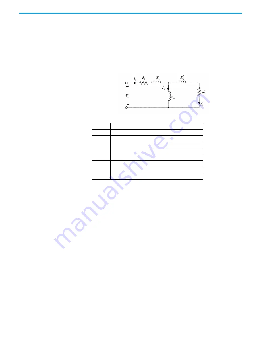
For induction motors, the Control Axis leverages the IEEE recommended
phase-neutral equivalent circuit motor model based on "Wye" configuration.
Reactance values, X, are related to their corresponding Inductance values, L,
by X =
w
L, where
w
is the rated frequency of the motor. The prime notation, for
example, X
2
', R
2
', indicates that the actual rotor component values X
2
, and R
2
are referenced to the stator side of the stator-to-rotor winding ratio.
Figure 3 - IEEE per Phase Motor Model
Table 4 - IEEE Phase Motor Model Diagram Designations
Control Modes
Velocity control is accomplished via three options for control mode:
•
Volts/Hertz (V/Hz)
•
Sensorless Vector
•
Velocity Vector
Volts/Hertz
Volts/Hz control is a simple, low-cost method for controlling variable
frequency drives (VFD), and is generally regarded as the most common VFD
control scheme. It’s suitable for both constant torque and variable torque
applications and can provide up to 150% of the rated torque at zero speed for
startup and peak loads. The magnetic field strength is proportional to the ratio
of voltage (V) to frequency (Hz), or V/Hz. The VFD controls the motor speed by
varying the frequency of the applied voltage, according to the synchronous
speed equation.
I
1
Stator current [Amps]
I
2
Rotor current [Amps]
R
1
Stator circuit resistance [Ohms]
R
2
Stator circuit resistance [Ohms]
X
1
Stator leakage reactance [Ohms]
X
2
Rotor circuit reactance [Ohms]
I
w
Magnetizing current [Amps]
X
w
Magnetizing reactance [Ohms]
V
1
Applied stator voltage [Volts]


