


External Tool Finishing Kit - Instruction Manual
l
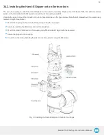
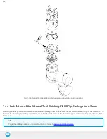
The robot contact surface (in blue) is the only contact point allowed between the Sensor and the robot for fastening the sensor to the
robot. Note that the inside ring must not touch the robot.
Info
Details on the bolt pattern and indexing pin for the tool side and the robot side can be found in the Specifications section of
the Force Torque Sensor Instruction Manual available on support.robotiq.com.
l
The screw positioning for the coupling and the robot mountings are shown in orange. See the Spare Parts section of the FT Sensor
Instruction Manual for a list of available Couplings.
l
M12 connector (pigtail or mounted) allows for both power and data transfer for the Sensor.
l
Status LED provides visual information on the status of the Sensor, see Status LED section of the FT 300 Force Torque Sensor Instruc-
tion Manual for details.
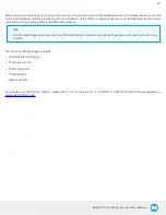
Fig. 1-7: FT 300 Force Torque Sensor force and torque diagrams.
The figure above represents the various force and torques that the FT 300 Force Torque Sensor can measure. Reference frame is
centered on the Sensor as shown above and visual inscriptions are also represented on it.
l
The Z axis passes through the center of the depression with positive direction in the tool direction.
l
The X axis traces a symmetric line centered on the connector; the positive direction points the opposite way away from the connector.
l
The Y axis uses the right hand thumb rule according to X-Z.
11