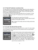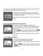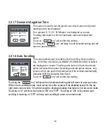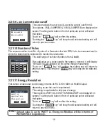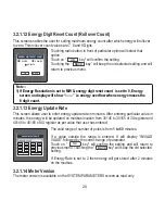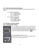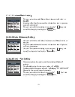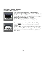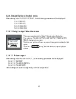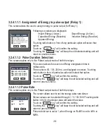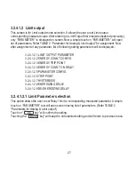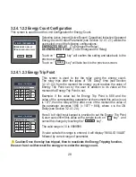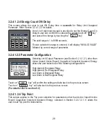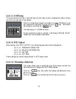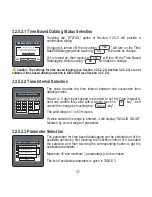
The allowable range is
10% to 120% for High Alarm
,
10% to 100%
for
Low Alarm
(refer
TABLE 2
).
Here 0 to 9 digit input keypad is provided to set the Trip Point & user
can confirm this value with a simple touch on “ key”. and cancel
the change by touching the “ key”.
If value outside the range is entered, it will display “INVALID VALUE”
followed by correct range of parameter.
ENTER TRIP POINT IN %
RELAY-1 TRIP POINT
ENTER
BACK
3.2.4.1.2.7 Hysteresis
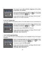
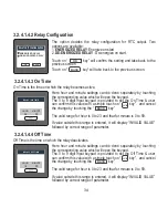
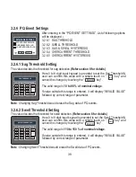
Here 0 to 9 digit input keypad is provided to set the Hysteresis & user
can confirm this value with a simple touch on “ key”. and cancel
the change by touching the “ key”.
The allowable range is
0.5% to 50.0 %
of Trip point.
If value outside the range is entered, it will display “INVALID VALUE”
followed by correct range of parameter.
(For details refer to section 9.2)
3.2.4.1.2.8 Energizing Delay
This screen allows the user to set Energizing Delay time in
seconds
for Relay Limit Assigned
Parameters.
SET HYSTERESIS IN %
RELAY-1 HYSTERESIS
.
ENTER
BACK
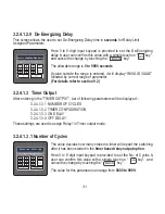
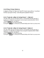
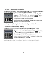
Here 0 to 9 digit input keypad is provided to set the Energizing Delay
& user can confirm this value with a simple touch on “ key”. and
cancel the change by touching the “ key”.
The allowable range is
0 to 9999 seconds
.
If value outside the range is entered, it will display “INVALID VALUE”
followed by correct range of parameter.
(For details refer to section 9.2)
ENTER
BACK
SET ENERGIZING DELAY IN SEC
RELAY-1 ENERGIZING DELAY
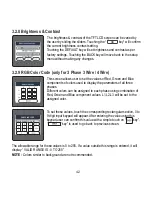
This screen applies to the Hysteresis selection. This screen allows the user to set Hysteresis for
relay output.
30
Summary of Contents for Master 3440iDL 0.2SS
Page 2: ......

