22
5000 Legacy Modbus ASCII Networking
This section details the 5000 legacy Modbus communications provided by the C500. This has been provided
to enable existing 5000 applications using Modbus to be replaced by the C500.
It is recommended that new installations use the better featured Modbus implementation (see Section 19).
The Modbus protocol was originally developed for use by Modicon programmable controllers but has been
adopted by many manufacturers as a common protocol standard.
The original Modicon standard specifies two transmissions modes: ASCII or RTU.
The C500 legacy modbus supports the ASCII transmission mode only.
The details of underlying communications protocol are generally looked after by the PLC directly. Please refer
to the offical Modbus documentation available from http://modbus.org/specs.php for more information on the
protocol.
All that is normally required for setup is to specify the addresses of the registers of interest to your application.
Much of the data from the C500 is implemented as 2 consecutive registers to make up a complete 32 bits of
data. Unless the C500 has been set up with a fullscale of more than 30000 units it is possible to only access
the lower order 16 bits contained in a single register.
Warning!
Be sure to correctly configure the indicator address in
SERIAL:NET.OPT:ADDRES
.
The indicator will not reply to messages that do not match its address.
22.1
Connection of the C500 Network
22.1.1
RS232 and RS422 Connection
When using the onboard serial ports see Sections 2.8 and 2.9 (C520 only). Alternatively, refer to the docu-
mentation supplied with your accessory module (see Section 15).
22.2
Modbus Register Definitions for the 5000
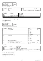
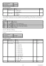
The C500 legacy Modbus implements a number of holding registers, input registers and coils. Generally all
that is required to configure your Modbus master to work with the C500 is to specify the address of the C500
unit, and the addresses of the registers that you are interested in.
Following is a list of the C500 Modbus registers.
22.2.1
Holding Registers
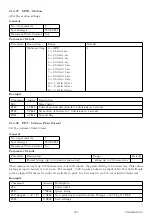
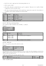
Holding registers in the C500 are as follows. Please note that the C500 supports additional setpoints to the
5000. These are accessable via registers 40017 to 40032.
Register
Contents
40001
Target 1 32 bits
40003
Inflight 1 32 bits
40005
Target 2 32 bits
40007
Inflight 2 32 bits
40009
Target 3 32 bits
40011
Inflight 3 32 bits
40013
Target 4 32 bits
40015
Inflight 4 32 bits
40017
Target 5 32 bits
40019
Inflight 5 32 bits
161
C500-600-2.0.3
Summary of Contents for C500 series
Page 1: ...C500 Series Digital Indicator Reference Manual ...
Page 54: ...8 3 Custom Format Tokens 8 3 1 Formatting 49 C500 600 2 0 3 ...
Page 56: ...230 Send time in format hh mm ss 231 Send Date in format dd mm yyyy 51 C500 600 2 0 3 ...
Page 123: ...118 C500 600 2 0 3 ...
Page 182: ...177 C500 600 2 0 3 ...

