background image

  Part V        Manual Operation


58                                                                                                    BECS-09  Singular-head  Computerized  Embroidery  Machine 


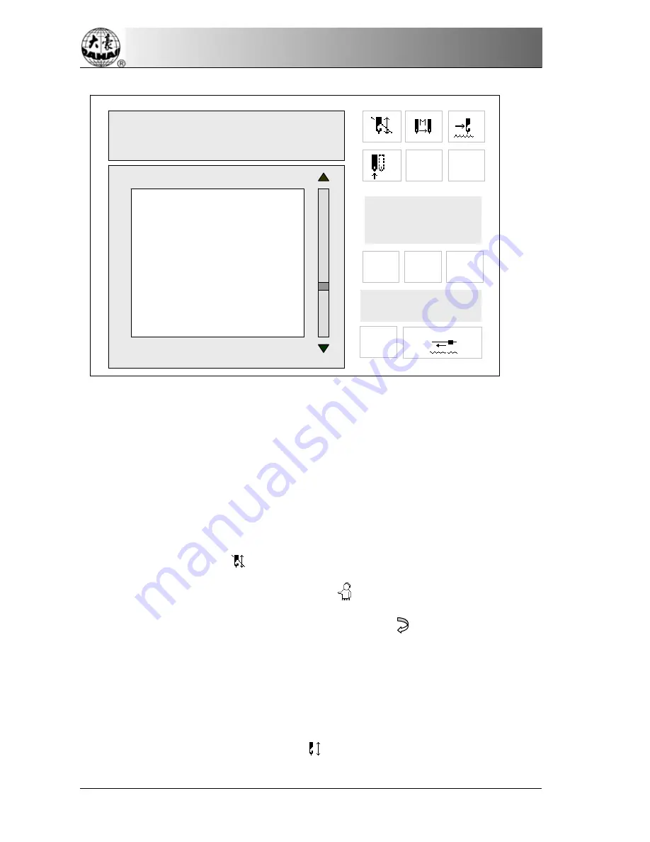
5.6 Embroider Range     

The user can do this operation after selecting the design. This is to 

embroider the design’s range and only available under the embroidery 

preparation mode. 

Operation: 

When the icon “

”(embroidery preparation) is shown in the main 

screen, press the manual operation key “

” to enter the manual operation 

menu. Then select “Emb. Range” and press the key “      ”. 

The system asks the user to input the stitch length for embroidering 

range. Press the numerical keys to input it. Its range is 10-60 (1=0.1 mms). 

 A moment later the system will return to the main screen. Now it’s under 

the embroidery confirmation mode “

” and the design number in the main 

Origin Back 

Return to stop point 

  Main axis point moving 

 Manual thread-trimming 

 Idling border 

 Embroider border 

 Embroider beeline 

  Positive stop code idling 

Backward Code Float 

300

51

Frame Range: 

 X +  54.5      Y +  14.6 
 X 

  23.1          .Y 

 76.3 


Startup to begin floating range 


# 01

COL:                      3 

STI:       11791 

P

X :   +                  123.5

Y :    +                  201.1 


9


Summary of Contents for RCM-1201PT

Page 1: ...RCM 1201PT Operating Manual...

Page 2: ...N 14 Part III Basic Knowledge and Operation 15 3 1 WORK MODE EMBROIDERY MODE AND WORK SEQUENCE 15 3 2 DESIGN INPUT FROM THE DISK AND STARTING THE FIRST EMBROIDERY 18 3 3 SELECT MEMORY DESIGN FOR EMBRO...

Page 3: ...IN 56 5 4 MANUAL TRIM 56 5 5 FRAME RANGE 56 5 6 EMBROIDER RANGE 58 5 7 EMBROIDER A LINE 59 5 8 FORWARD CODE FLOAT 60 5 9 BACKWARD CODE FLOAT 61 5 10 FORWARD STI FLOAT 61 5 11 BACKWARD STI FLOAT 62 Par...

Page 4: ...7 4 DISK INPUT 79 7 5 DELETE MEMORY DESIGN 80 7 6 EDIT BATCH DESIGN 81 7 7 COPY DESIGN 87 7 8 COMBINE DESIGN 89 7 9 DIVIDE DESIGN 92 7 10 CLEAR ALL 95 7 11 CHECK DESIGN 96 7 12 RENAME FILE 97 7 13 EX...

Page 5: ...Index IV BECS 09 Singular head Computerized Embroidery Machine 8 6 MACHINE SELF TEST AND TEST MACHINE PARTS 106 Appendix 108...

Page 6: ...mat disk and files in binary system ternary system and Z coding system from Barudan format disk And it is also possible to output the design data of binary system from the memory to Tajima format disk...

Page 7: ...odes 8 Over frame protection It s to prevent the frame from exceeding the normal scope to cause a collision accident 9 Auto origin return With this function the frame will return to the origin point u...

Page 8: ...of wrong operations or machine malfunctions the screen will show words or icons to inform you 17 Frame protection When the frame has changed its position after power off during embroidering or after...

Page 9: ...l designs with their different parameter setting Thus the combined designs can be embroidered together 21 Cyclic embroidery With this function the machine will automatically return to the origin point...

Page 10: ...Part II Control and Basic Operations BECS 09 Singular head Computerized Embroidery Machine 5 STI 51 Part II Control and Basic Operations 2 1 Control Panel 01 COL 3 STI 11791 P F X 123 5 Y 201 1 9...

Page 11: ...Part II Control and Basic Operations 6 BECS 09 Singular head Computerized Embroidery Machine Start button Stop button Emergency Stop button...

Page 12: ...on mode and means embroidery confirmation mode The mode is for preparation work and in this mode the user can press the start button to begin embroidery After that it s no longer allowed to select des...

Page 13: ...idling Press the key to switch among them It shows the current needle position Press the number key to change color and the current needle position will show in this area e g press the numerical key...

Page 14: ...y The machine stops because the stop button is pressed The machine stops after it returns and then patching embroiders to the thread break point The following items are also shown in the main screen 1...

Page 15: ...r Add Stitch to reset the count Otherwise press ESC to exit operation 5 Frame coordinate It can set the last design s frame position as the zero point of coordinates like X 123 5 Y 201 1 in the above...

Page 16: ...ations including scaling up down design direction rotation angle repetition priority repetition times repetition interval offset origin cyclic embroidery and work sequence The other page is for standa...

Page 17: ...dery method Press this key to switch among normal embroidery high speed floating and low speed floating Numerical keys Keys 0 1 9 are used to input design number design name and various data parameter...

Page 18: ...he angle bisector In all function and menu operations press to move the cursor in the horizontal direction or to turn page while pressing move the cursor in the vertical direction 3 Direct control key...

Page 19: ...o stop in the stop area before starting embroidery returning moving frame etc The user can manually turn the shaft to the position 2 5 Start and Stop Button The start button green is on the operation...

Page 20: ...longer permitted to select design input scale and repetition parameters etc which will affect the design embroidery Under mode press the key to enter the embroidery confirm mode under mode press the k...

Page 21: ...titches are embroidered onto the fabric to form designs Press the stop button in embroidery and the machine will stop If the frame return is permitted in parameter setting press the stop button when t...

Page 22: ...the current stitch count The user has to ensure before embroidery that the system is in normal embroidery mode 3 Work sequence Threads of different colors are required for a complicated design This is...

Page 23: ...ry Input of disk designs to memory can be done both in design and disk operations And here take an example from design operation Operation 1 Press to enter the memory design operation menu and insert...

Page 24: ...n pages then press to move the cursor to select the design and press to confirm 4 The machine automatically provides and displays the smallest number available for the new memory design It s possible...

Page 25: ...can be done If the user wants to change the design number he can press 5 The system asks for input of the memory design name If it s the same to its disk name press otherwise move the cursor to the se...

Page 26: ...tion of parameter input if the system is under embroidery preparation mode the system will ask whether to embroider the latest input design if it is under embroidery confirmation mode Design Free Stit...

Page 27: ...he parameter menu for parameter setting Design Free Stitch 201952 Select Design Show Memory Design Disk Input Delete Design Edit Batch Design Copy Design Combine Design Divide Design Clear All Design...

Page 28: ...before embroidery You need to do the follow work too before embroidery Set the fabric ready and press to move the frame to the beginning position Ensure that the system is under normal embroidery mod...

Page 29: ...ode If not press and to return to the embroidery preparation mode press to enter the design operation menu Press to enter the first menu item and the following prompt will appear If you have known the...

Page 30: ...ss to clear and then input select a new number If you press according to the prompt in the above menu you haven t input the design number or have pressed to clear the input number the design directory...

Page 31: ...creen will switch into the parameter menu PU PD Origin point has been saved Memory Design Design Count 01 FISH 11791 1 26 02 2 11791 1 Free Stitch 03 3 4796 4 201952 04 3 63523 6 05 3 10023 3 06 3 236...

Page 32: ...you don t change the parameters you can press ESC key to exit Refer to Part IV for parameter setting 5 In the above operations you can press ESC to return to the main screen at any time After selectin...

Page 33: ...ss The parameters except the 7th and 8th in the first page are set and stored with each design separately Operation Press to enter the parameter setting menu Or after you select the design for embroid...

Page 34: ...cal key to select it and press the confirmation key to enter its sub menu 4 2 Real Time Rotation and Scaling up down This parameter is to set image scales rotation direction and angle for embroidery O...

Page 35: ...ove menu screen press to set the scale in the direction A cursor _ appears in the screen Input numbers to set the X scale 50 200 E g 1 2 and 0 are for Parameter Scales X 100 Y 100 Direction P Rot Angl...

Page 36: ...le where there is a cursor _ It is as the follows Parameter Scales X 120 Y 100 Direction P Rot Angle 0 Rep Prior X Rep Times X 1 Y 1 R Interval X 0 0 Y 0 0 Offset Org No Cyclic Emb No Work Sequence Pa...

Page 37: ...on A square cursor appears in the screen It is as follows Press to select one of the eight directions for the design e g select Parameter Scales X 120 Y 160 Direction P Rot Angle 0 Rep Prior X Rep Tim...

Page 38: ...ch is marked by a cursor Input the new value of the rotation angle between 0 and 89 by pressing Parameter Scales X 120 Y 160 Direction b Rot Angle 0 Rep Prior X Rep Times X 1 Y 1 R Interval X 0 0 Y 0...

Page 39: ...oves to another position to embroider the last finished design again The maximum repetition times in each of X and Y direction is 99 So the maximum total repetition is 9801 Operation Under the mode en...

Page 40: ...s to set the parameter Repetition times Input the number where there is a cursor Parameter Scale X 120 Y 160 Direction b Rot Angle 45 Rep Prior X Rep Times X 1 Y 1 R Interval X 0 0 Y 0 0 Offset Org No...

Page 41: ...value as 3 Input the new repetition times 1 99 for Y direction E g press 2 and Parameter Scale X 120 Y 160 Direction b Rot Angle 45 Rep Prior Y Rep Times X 1 Y 1 R Interval X 0 0 Y 0 0 Offset Org No...

Page 42: ...g press 1 and 2 to set the value as 12 mm and then press to confirm The system will show you to set the new Y direction interval Parameter Scale X 120 Y 160 Direction b Rot Angle 45 Rep Prior Y Rep Ti...

Page 43: ...nt The offset point is set under all modees except the embroidery confirmation mode It can be any point except start point See the following picture Parameter Scale X 120 Y 160 Direction b Rot Angle 4...

Page 44: ...l begin After embroidery the machine stops Press the start button again and the frame will return to the offset point a if the frame hasn t return to the point a already and whether auto origin point...

Page 45: ...following picture will be shown 4 5 Cyclic Embroidery Press the key to set the cyclic embroidery A square cursor will show where to input Frame To Offset Then Press x 0 0 Y 0 0 Parameter Scale X 120 Y...

Page 46: ...rk Sequence Work sequence is a function set to improve the embroidery efficiency and change color automatically Based on design s color blocks it can be set according to the color difference or the us...

Page 47: ...he work sequence The cursor __ will show you where to input Input the numbers which can t be larger than 15 To input a number larger than 10 press the key 10 first and then another digit After the cor...

Page 48: ...s If Circulate the setting before is set as No the following setting will keep unchanged If it is set as Yes the setting after the cursor will repeat the setting before continuously Parameter Scale X...

Page 49: ...ss than the set value there will be jumping and no trim if the continuous stitches are larger than or the same as the set value there will be jumping to trim When it is jumping and no trim the machine...

Page 50: ...he machine will automatically return when the machine detects a thread break and stops automatically in case Thr Broken Detect is set 3 7 If the parameter value is 0 there will be no returning If the...

Page 51: ...read break during jump stitch in embroidery Long Sti Divide Options No 7 12 This parameter is to decide whether to divide the long stitches in embroidery and the stitch length in dividing If the stitc...

Page 52: ...d of embroidery and for operations like color change and over frame Some types of machines aren t equipped with auto trim device Length After Trim Options 1 4 This parameter is to adjust the length of...

Page 53: ...om moving away in the last stitch before trimming This parameter is to decide whether to lock stitch before trimming Lock Num Af Trim Options 0 1 2 This parameter is to set how many stitches to lock a...

Page 54: ...he machine will automatically set according to the size of stitch codes Shift Sti Length Options 2 7 Standard Machine Parameter Maximum Speed 850 Minimum Speed 450 Shift Sti Length 3 Frame Curve Angle...

Page 55: ...aximum Speed for every more mm of stitch length When the stitch increases to 12 mm the speed will decrease to the Minimum Speed The three parameter values should be set according to the real situation...

Page 56: ...tup stitches The larger the parameter value is the more quickly the machine speed rise from the startup speed to the maximum speed Adjust Speed Options 1 5 This parameter is to make the real speed nea...

Page 57: ...uld be No Sequin Embroidery Options Yes No This parameter is set for the machines equipped with sequin embroidery devices The parameter should be set as Yes for the machines with such devices Otherwis...

Page 58: ...s Yes No When this parameter is set as Yes there will appear at the end of embroidery a prompt Return to start point or offset point press any key to continue If press a key and the frame hasn t been...

Page 59: ...st manual frame moving The user can choose according to the need Low Manual Frame Options 0 9 This parameter is to set the speed for the low manual frame moving Stop To Color Read Options Yes No This...

Page 60: ...igin Back and click to confirm and then the machine will automatically return to the start point 5 2 Stop Back If the frame has been moved or other operations have been performed after the machine sto...

Page 61: ...l rotate to stop near 100 which can also be performed by pressing shortcut key on the panel At this time the indicator LED is on and the embroidery can start after the startup key is pressed 5 4 Manua...

Page 62: ...to the main screen If the user wants to exit the operation during the above process he can press ESC and the display will return to the main screen After selecting a design the user can use this opera...

Page 63: ...ect Emb Range and press the key The system asks the user to input the stitch length for embroidering range Press the numerical keys to input it Its range is 10 60 1 0 1 mms A moment later the system w...

Page 64: ...tion Emb a Line Or directly press the key 7 to select it And then press the confirmation key The system asks the user to input the stitch length for embroidering a line Press the numerical keys to inp...

Page 65: ...the design quickly so as to let the machine start embroidery from any point Operation When the machine stops under the embroidery confirmation mode select the option Forward Code Float in the first s...

Page 66: ...dery confirmation mode select the option Backward Code Float in the first screen of manual operation menu press the confirmation key and then the machine will float backward to the last stop code or c...

Page 67: ...a prompt in the screen asking the user to input the stitches to float Press the numerical keys to input the stitches for floating Press the confirmation key and then the frame will move forward the i...

Page 68: ...confirmation key and then there will be a prompt in the screen asking the user to input the stitches to float Press the numerical keys to input the stitches for floating Press the confirmation key an...

Page 69: ...ayed press the key to enter the disk management menu Press the key 1 and the confirmation key to list the directory of disk files 1 for files in floppy disk 4 for files in USB flash disk and 7 for fil...

Page 70: ...DSZ in floppy disks of TAJIMA format or BARUDAN FDR format and input the design files to the machine memory After this operation the scale parameter will be restored to the standard value refer to ap...

Page 71: ...Press the key to select a design and press to confirm the selection Then the system will provide and display an available design number minimum which the user can change For example if the system pro...

Page 72: ...sk Free stitch 201952 Disk Des List Disk Des Input PC COM Des Input U Des List U Des Input Delete U Design Usb Disk Des List Usb Disk Des Input Delete Usb Disk Design Disk Name DH01 Memory No 20 Memor...

Page 73: ...ation mode the system will ask whether to embroider the input design immediately Press to select Yes then press and the system will enter the parameter setting operation Disk Free stitch 201952 Disk D...

Page 74: ...instructions from PC 3 Select a design and transfer it via third party punch software 6 4 Delete USB Floppy Disk Design This is to delete from the Tajima format disks the design files in formats of D...

Page 75: ...creen to enter the disk management menu Then turn to the second page 2 Press and the system will ask to input the memory No of the design for output Press 4 and for output to USB flash disk Press 6 an...

Page 76: ...tem will display its memory name and ask to input its disk name If the user wants to use the design s memory name as its disk name press the key Otherwise press and to select characters and then press...

Page 77: ...4M Disk or 3 to select Format 720k Disk or 5 to select Format U Disk or 7 to select Format Usb Disk Press to confirm the operation of formatting A progress bar will appear and after the formatting the...

Page 78: ...Part VI Disk Management BECS 09 Singular head Computerized Embroidery Machine 73 displayed in darkness...

Page 79: ...e and the embroidery confirmation mode But some menu options are displayed in darkness in some cases when they are unavailable to operation Operation Under the main screen press to enter the design op...

Page 80: ...nd the embroidery preparation mode press the key to enter the design operation menu Press the confirm key to enter the first menu option The following prompt will appear If the design s memory No is k...

Page 81: ...ign If the user press directly without inputting a number or after pressing to cancel the input the directory of memory designs will be displayed on the screen Press keys to select a design intended f...

Page 82: ...any time 7 3 Show Memory Design This operation is to list the memory designs and show their parameters Operation Under the main screen press to enter the memory design operation menu Press 2 or to mov...

Page 83: ...coordinates of the 4 boundary lines coordinates of the stop point number of design colors and number of stitches The design can also be displayed in different ways to show details clearly Des No 02 X...

Page 84: ...confirm the selection Then the system will provide and display an available design number minimum which the user can change For example if the system provides a minimum number 20 and the user wants to...

Page 85: ...ut design immediately To embroider a new design press to select Yes then press and the system will enter the parameter setting operation Refer to Part IV for parameter setting To embroider the origina...

Page 86: ...lected design 7 6 Edit Batch Design This operation is to edit batch design Design interval is the distance from the start point of the current design to the start point of the first design Operation U...

Page 87: ...by a batch design in the memory The number with ___ below hasn t been used for design number and is available to new batch designs Press a key chosen from a to i to input the batch design number The...

Page 88: ...irectory and press to select design Refer to Part III Press the key to confirm the selection Design Free stitch 201952 Select Design Show Memory Design Disk Input Delete Design Edit Batch Design Copy...

Page 89: ...mber the same operation to the first design and the system will ask to input the X direction interval Design Free stitch 201952 Select Design Show Memory Design Disk Input Delete Design Edit Batch Des...

Page 90: ...4 11791 1 Free Stitch 03 25 4796 3 201952 04 26 3523 2 05 27 10023 1 06 28 2367 2 07 29 10006 3 08 30 6745 1 09 31 10002 2 Design Free stitch 201952 Select Design Show Memory Design Disk Input Delete...

Page 91: ...to the parameters To change a parameter value move the cursor to the parameter press and do according to operations 5 to 7 To exit in the process press ESC to return to the design operation menu When...

Page 92: ...it as a new design in the memory Operation Under the main menu press to enter the memory design operation menu Press 6 to select the sixth option Copy Design Press and the system will ask for the mem...

Page 93: ...e system will provide a minimum vacant design number for the new design The user can input a new number by pressing numerical keys and then If the input number has been used by another design confirma...

Page 94: ...eration Under the main screen press to enter the memory design operation menu and then select the seventh option Combine Design and press Design Free stitch 201952 Select Design Show Memory Design Dis...

Page 95: ...input the design number of the second design 3 Input the memory number of the second design in the same way with operation 2 Then the system will provide and display the minimum available memory numb...

Page 96: ...he interval between the two designs Design Free stitch 201952 Select Design Show Memory Design Disk Input Delete Design Edit Batch Design Old Des No 1 01 Old Des No 2 03 New Des No 21 X interval 10 5...

Page 97: ...ation the system will return to the design editing menu 7 9 Divide Design This operation is to divide one design into two and save them in the memory Operation Under the main screen press to enter the...

Page 98: ...s and the system will provide and display a minimum available design number Design Free stitch 201952 Select Design Show Memory Design Disk Input Delete Design Edit Batch Design Old No 01 Div Stitch 0...

Page 99: ...n before the dividing point as the first new design And the system will ask to input the number of the second new design Confirm the system provided number or input a new number and confirm Then the s...

Page 100: ...the system will return to the design operation menu 7 10 Clear All This is to delete all the designs in the memory Please take caution Operation Under the main screen and the mode press to enter the...

Page 101: ...nd judge the malfunction cause Operation Under the main screen press to enter the memory design operation menu Then press to turn to the second page The cursor is before the option Check Design Press...

Page 102: ...wing screen will appear Input a new design file name for the selected design Design Free stitch 201952 Check Design Rename Filename Expand Satin Des Letter pattern Design No 01 Choose Design Free stit...

Page 103: ...tion menu 7 13 Expand Satin On the second screen of design operation menu there is an option for expanding satin to create a new design This function is designed to compensate for the satin stitch dif...

Page 104: ...and digits 0 9 The user can arrange the letters and digits at will to make a new design Operation 1 Enter the second page of the design operation menu and select the option Des letter pattern The fol...

Page 105: ...degree for Angle After setting press ESC to enter the next step When Arc is selected for Arrange the computer will ask to input the parameters for the arc including the coordinates of the start middl...

Page 106: ...t Yes and then press Yes to enter the next step The system creates the letter design and display it in the screen Press Esc to exit the display The system ask whether to save the letter design No is t...

Page 107: ...ys and to enter different submenus To exit from the assistant management menu press ESC key to return to the main screen 8 1 Set soft Limit This function is to set the embroidery range of the frame by...

Page 108: ...ve the frame to a point and press to set the point as the top left point Assistance function Set Soft Limit Frame Restore Default Setup Set Frame Origin no set Machine Self Test Test Machine Parts set...

Page 109: ...ame to the position where the frame was when power off so as to continue embroidery If the origin point hasn t been set the option Frame Restore will be in darkness and unavailable for operation If th...

Page 110: ...istant management menu Press keys to select the option Default Setup Press to restore default setup and then return to the assistant management menu Otherwise press Esc to exit the operation and retur...

Page 111: ...and the frame will move to the origin point and then back After this the option Set Frame Origin in the assistant function menu is followed by have set and the second option Frame Restore is in bright...

Page 112: ...107 the mechanical parts Refer to the maintenance manual for details 8 7 Set Password Setting password can protect the machine from the undesired results from accidental parameter changes After passw...

Page 113: ...ion Rotation angle 0 89 0 Repetition Parameters Parameter Choice Standard value Rep Prior Rep Times X 1 99 1 Rep Times Y 1 99 1 Repetition Interval X 999 9 999 9 0 Repetition Interval Y 999 9 999 9 0...

Page 114: ...int E 13 Not exit embroidery confirm E 14 Memory parameter lost E 15 Memory design lost E 16 No design in memory E 17 No free design numbers E 18 Memory design number does not exist E 19 No enough mem...

Page 115: ...hine E 60 Frame software limit E 63 No frame moving angle E 70 No zero point signal E 74 Cutter not in the right position E 75 Trimming motor overtime E 220 Special malfunction 0 E 221 Special malfunc...

Page 116: ...the error persists after perfoming the procedure you may need to contact your technician for further assistence All material on this manual are intended solely for personal noncommercial use by the u...

Reviews: