Rev. 1.00, 09/03, page 410 of 704
14.5.7
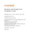
Set Timing for Overflow Flag (OVF)
The overflow flag (OVF) in TWCR2 is set to 1 by the overflow signal which is output when
TCNT overflows from H
′
FF to H
′
00. Figure 14.9 shows the OVF set timing.
OVF
Overflow signal
TWCNT
N'00
N'FF
Figure 14.9 Set Timing for OVF Flag
14.6 Interrupt
Sources
The duty measurement circuit can request two interrupts: TWOVI and TWENDI. Table 14.2 lists
the sources and priorities of these interrupts. Each interrupt can be enabled or disabled by an
interrupt enable bit in TCR or TCSR. Independent signals are sent to the interrupt controller for
each interrupt.
Table 14.2 Interrupt Sources for Duty Measurement Circuit
Interrupt
Interrupt Source
Interrupt Flag
Priority
TWENDI
Duty measurement end
ENDF
High
TWOVI TWCNT
overflow
OVF
Low
Summary of Contents for H8S/2437
Page 2: ...Rev 1 00 09 03 page ii of xxxviii ...
Page 8: ...Rev 1 00 09 03 page viii of xxxviii ...
Page 32: ...Rev 1 00 09 03 page xxxii of xxxviii ...
Page 38: ...Rev 1 00 09 03 page xxxviii of xxxviii ...
Page 168: ...Rev 1 00 09 03 page 130 of 704 ...
Page 336: ...Rev 1 00 09 03 page 298 of 704 ...
Page 402: ...Rev 1 00 09 03 page 364 of 704 ...
Page 454: ...Rev 1 00 09 03 page 416 of 704 ...
Page 512: ...Rev 1 00 09 03 page 474 of 704 ...
Page 562: ...Rev 1 00 09 03 page 524 of 704 ...
Page 648: ...Rev 1 00 09 03 page 610 of 704 ...
Page 672: ...Rev 1 00 09 03 page 634 of 704 ...
Page 732: ...Rev 1 00 09 03 page 694 of 704 ...
Page 742: ...Rev 1 00 09 03 page 704 of 704 ...
Page 745: ......
Page 746: ...H8S 2437 Group Hardware Manual REJ09B0059 0100Z ...