Systems
£
¤
¥
¦
The fuel system consists of a fuel tank, fuel fi ll fi ttings, fuel hoses,
fuel vents, anti-siphon valve, internal tank valves, fuel fi lter, fuel gauge
and sender. Each one of these components plays an important role
in providing an uninterrupted fl ow of fuel while operating your boat.
Refer to the technical drawing section for system specifi cs.
Fuel Tank
Select overseas vessels use a polyster tank.
Boats manufactured for
domestic use are now required to be EPA compliant and will be outfi tted with an
aluminum tank.
This system uses parts such as a valve located inside
the fuel tank and can not be serviced. Also, there is a carbon canister
which functions much like the one in an automobile located between
the fuel tank and hull side vent. This canister under normal usage
requires no service. These tanks are tested along with the complete
fuel system for safety requirements and quality in house. Also, they are
inspected independently by National Marine Manufacturers Association
personnel.
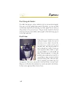
The fuel fi ll fi tting is labeled “gas” and in addition displays the
international symbol (See the next page). When fueling the boat keep
the fi ll nozzle in contact with the fuel fi ll pipe since it decreases static
electricity. Always use the recommended fuel octane rating as specifi ed
in your engine owner’s manual.
Extinguish all fl ame producing agents before fueling!
Fuel System
Fuel Fill
Summary of Contents for 29 OBX
Page 1: ...OWNER S MANUAL OWNER S MANUAL 29 OBX 29 OBX REGAL 281760 REGAL 281760 3 2016...
Page 2: ...THIS PAGE IS LEFT INTENTIONALLY BLANK...
Page 7: ...INT 7 Introduction THIS PAGE IS LEFT INTENTIONALLY BLANK...
Page 18: ...INT 18...
Page 38: ...u v u w CHAPTER 1 NAVIGATION LIGHT RULES...
Page 41: ...Safety On Board...
Page 94: ...Engine Controls 3 27 Typical Switch Shown Above...
Page 96: ...Engine Controls 3 29...
Page 162: ...Equipment Operation X Y Z Typical Dual Battery Switch Circuitry Front View...
Page 163: ...CHAPTER 6 _ Dual Battery Switch Circuitry Rear View...
Page 171: ...CHAPTER 6 CANVAS TRAVEL COVER...
Page 182: ...Equipment Operation Depth Gauge With Functions...
Page 196: ...Equipment Operation...
Page 257: ...Cosmetic Care Maintenance 7 35 Notes...
Page 262: ...Troubleshooting 8 5...
Page 263: ...CHAPTER 8 8 6...
Page 264: ...Troubleshooting 8 7...
Page 265: ...CHAPTER 8 8 8 0 1 0 2 3 4 5 6 2 4 6 7 8 9 2 3...
Page 273: ...CHAPTER 9 Notes...
Page 294: ...Technical Information 12 3 TYPICAL LABELS LOCATIONS Power Tower...
Page 299: ...Technical Information...
Page 305: ...Technical Information Note Locate per Splash...
Page 306: ...Technical Information...
Page 310: ...Technical Information TYPICAL HULL HARNESS BREAKOUT...
Page 311: ...Technical Information TYPICAL SWITCH PANEL BREAKOUT...
Page 312: ...Technical Information TYPICAL DASH CHARTPLOTTER BREAKOUT...
Page 313: ...Technical Information TYPICAL GARMIN YAMAHA NEMA 2000 NETWORK...
Page 324: ...Technical Information...


