Vessel Operation
5-19
In short, it is
a way of fi ne-tuning the ride of your boat and will enable
you to get the most effi cient and comfortable ride possible, whatever
the conditions.
Use Of Power Trim
The power trim is normally used prior to accelerating onto a plane, after
reaching the desired RPM or boat speed and when there is a change
in water or boating conditions. Position passengers and equipment in
the boat so that the weight is balanced correctly fore and aft as well
as side to side. Trimming will not compensate for an unbalanced load.
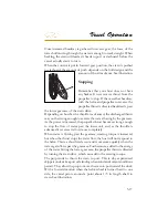
To operate the trim, push the switch until the desired bow position is
reached. The trim may be operated at any boat speed or at rest. Avoid
operating the trim system when running in reverse. Observe the trim/
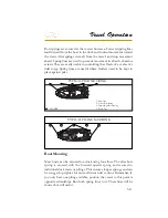
tilt gauge which indicates the boat’s bow position achieved by the trim
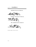
angle of the vertical drive unit. “Bow-Up” corresponds to the upper
portion of the trim range on the gauge while “Bow Down” corresponds
to the lower portion of the trim range on the gauge.
To determine the proper trim angle, experiment a little until you are
familiar with the changes in your boat. The vessel will be properly
trimmed when the trim angle provides the best boat performance for
the particular operating conditions. A trim position that provides a
balanced steering load is desirable.
To familiarize yourself with the power trim, make test runs at slower
speeds and at various trim positions to see the effect of trimming.
Note the time it takes for the boat to plane. If available, view the
chartplotter screen tachometer and speedometer readings as well as
the ride action of the boat.
Summary of Contents for 29 OBX
Page 1: ...OWNER S MANUAL OWNER S MANUAL 29 OBX 29 OBX REGAL 281760 REGAL 281760 3 2016...
Page 2: ...THIS PAGE IS LEFT INTENTIONALLY BLANK...
Page 7: ...INT 7 Introduction THIS PAGE IS LEFT INTENTIONALLY BLANK...
Page 18: ...INT 18...
Page 38: ...u v u w CHAPTER 1 NAVIGATION LIGHT RULES...
Page 41: ...Safety On Board...
Page 94: ...Engine Controls 3 27 Typical Switch Shown Above...
Page 96: ...Engine Controls 3 29...
Page 162: ...Equipment Operation X Y Z Typical Dual Battery Switch Circuitry Front View...
Page 163: ...CHAPTER 6 _ Dual Battery Switch Circuitry Rear View...
Page 171: ...CHAPTER 6 CANVAS TRAVEL COVER...
Page 182: ...Equipment Operation Depth Gauge With Functions...
Page 196: ...Equipment Operation...
Page 257: ...Cosmetic Care Maintenance 7 35 Notes...
Page 262: ...Troubleshooting 8 5...
Page 263: ...CHAPTER 8 8 6...
Page 264: ...Troubleshooting 8 7...
Page 265: ...CHAPTER 8 8 8 0 1 0 2 3 4 5 6 2 4 6 7 8 9 2 3...
Page 273: ...CHAPTER 9 Notes...
Page 294: ...Technical Information 12 3 TYPICAL LABELS LOCATIONS Power Tower...
Page 299: ...Technical Information...
Page 305: ...Technical Information Note Locate per Splash...
Page 306: ...Technical Information...
Page 310: ...Technical Information TYPICAL HULL HARNESS BREAKOUT...
Page 311: ...Technical Information TYPICAL SWITCH PANEL BREAKOUT...
Page 312: ...Technical Information TYPICAL DASH CHARTPLOTTER BREAKOUT...
Page 313: ...Technical Information TYPICAL GARMIN YAMAHA NEMA 2000 NETWORK...
Page 324: ...Technical Information...

