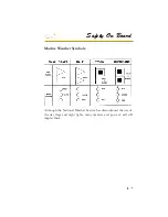
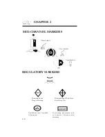


CHAPTER 3
3-4
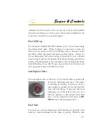
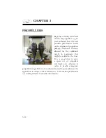
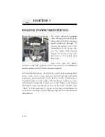
Impeller/ Water Pump
Periodically, the coolant system’s impeller and water pump should
be inspected for debris, damage or excessive wear due to use, water
chemistry such as mineral and/or silt conditions. Damaged parts will
affect the system’s ability to function, and may cause engine overheating
or damage. Contact your closest Regal dealer for more information
and maintenance schedules of key outboard engine systems.
Thermostat
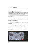
If the temperature gauge starts yielding abnormal readings, it may
become necessary to look at or replace the powerhead thermostat after
determining whether it is functioning properly. The thermostat reads
the temperature of coolant and determines whether to open or close a
valve to allow warm sea water to pass into the exhaust manifold. The
thermostat may recirculate hot coolant for the purposes of reaching
standard operating temperatures. If standard operating temperatures
have been reached, the thermostat will open a valve and allow hot raw
water to exit through the exhaust manifold. For more information
read your outboard engine manual or contact the closest Regal dealer
.Dealers have the necessary knowledge and tools to troubleshoot any
engine related problems
.
/
0
1
2
3
0
4
5
6
1
7
8
3
6
9
3
6
9
:
;
0
<
3
.
3
0
:
1
3
<
5
0
;
=
0
7
9
7
3
<
>
6
1
?
9
3
6
9
9
7
8
1
7
9
1
<
0
7
@
6
0
3
A
.
/
0
1
2
:
4
7
7
1
7
8
3
6
9
9
7
8
1
7
9
>
1
3
6
0
4
3
.
B
4
7
5
3
1
0
7
1
7
8
3
6
9
:
;
0
<
3
.
3
C
.
<
1
3
;
.
D
0
/
9
:
6
9
.
3
A
Summary of Contents for 29 OBX
Page 1: ...OWNER S MANUAL OWNER S MANUAL 29 OBX 29 OBX REGAL 281760 REGAL 281760 3 2016...
Page 2: ...THIS PAGE IS LEFT INTENTIONALLY BLANK...
Page 7: ...INT 7 Introduction THIS PAGE IS LEFT INTENTIONALLY BLANK...
Page 18: ...INT 18...
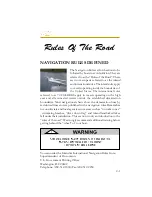
Page 38: ...u v u w CHAPTER 1 NAVIGATION LIGHT RULES...
Page 41: ...Safety On Board...
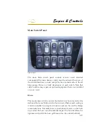
Page 94: ...Engine Controls 3 27 Typical Switch Shown Above...
Page 96: ...Engine Controls 3 29...
Page 162: ...Equipment Operation X Y Z Typical Dual Battery Switch Circuitry Front View...
Page 163: ...CHAPTER 6 _ Dual Battery Switch Circuitry Rear View...
Page 171: ...CHAPTER 6 CANVAS TRAVEL COVER...
Page 182: ...Equipment Operation Depth Gauge With Functions...
Page 196: ...Equipment Operation...
Page 257: ...Cosmetic Care Maintenance 7 35 Notes...
Page 262: ...Troubleshooting 8 5...
Page 263: ...CHAPTER 8 8 6...
Page 264: ...Troubleshooting 8 7...
Page 265: ...CHAPTER 8 8 8 0 1 0 2 3 4 5 6 2 4 6 7 8 9 2 3...
Page 273: ...CHAPTER 9 Notes...
Page 294: ...Technical Information 12 3 TYPICAL LABELS LOCATIONS Power Tower...
Page 299: ...Technical Information...
Page 305: ...Technical Information Note Locate per Splash...
Page 306: ...Technical Information...
Page 310: ...Technical Information TYPICAL HULL HARNESS BREAKOUT...
Page 311: ...Technical Information TYPICAL SWITCH PANEL BREAKOUT...
Page 312: ...Technical Information TYPICAL DASH CHARTPLOTTER BREAKOUT...
Page 313: ...Technical Information TYPICAL GARMIN YAMAHA NEMA 2000 NETWORK...
Page 324: ...Technical Information...


